|
| |
2-1
TM 10-4930-238-12&P
Chapter 2
OPERATING INSTRUCTIONS
Section I
DESCRIPTION AND USE OF OPERATOR’S CONTROL AND INDICATORS
Section II
PREVENTIVE MAINTENANCE CHECKS AND SERVICES
Section III
OPERATION UNDER USUAL CONDITIONS
Section IV
OPERATION UNDER UNUSUAL CONDITIONS
Section I. DESCRIPTION AND USE OF OPERATOR’S CONTROLS AND
INDICATORS
Para.
Para.
Introduction . . . . . . . . . . . . . . . . . . . . . . . . . . . . 2–1
Pumping Assembly Controls and Indicators . . . . . . . 2–3
Elbow Coupler Valve and Butterfly
Valve Assembly . . . . . . . . . . . . . . . . . . . . 2–2
Filter Separator Controls and Indicators . . . . . . . . . . 2–4
2–1.
INTRODUCTION.
This section describes the controls and indicators you, as the operator, will be using most often. Most of the controls
and instruments used are located on individual assemblies that make up the Forward Area Refueling Equipment.
Table 2–1 will give you a brief description of each control or instrument.
2–2.
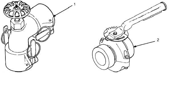
ELBOW COUPLER VALVE AND BUTTERFLY VALVE ASSEMBLY.
(Refer to Figure 2-1 and Table 2-1.)
Figure 2–1. Operator’s Valve Controls.
|