|
| |
TM 10-4320-348-14
(2)
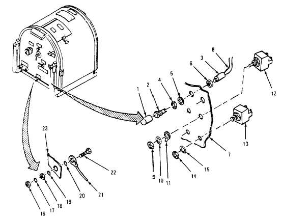
Removal.
(a)
Remove four hex nuts (2), four lock washers (3), and four machine screws (4) securing intervehicle
connector (1) to sound enclosure rear panel assembly (5).
(b)
Remove intervehicle connector (1) from sound enclosure rear panel assembly (5).
(c)
Repair is limited to replacement of defective parts.
(3)
Installation.
(a)
Install intervehicle connector (1) into rear sound enclosure rear panel assembly (5).
(b)
Secure intervehicle connector (1) to sound enclosure rear panel assembly (5) with four machine screws (4),
four lock washers (3) and four hex nuts (2).
Figure 4-10. Lights, Toggle Switches, and Circuit Breaker Replacement
b.
Terminal Blocks.
(1)
Inspection.
Inspect the terminal block, located at the lower right rear of the frame below the intervehicle connector, for
damage. Replace if damaged.
4-28
|