|
| |
TM 10-4320-342-24
4-4. STARTER-GENERATOR REPAIR - continued.
(e)
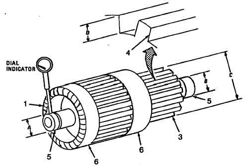
Place dial indicator on bearing journals (5) and rotate armature slowly for one complete turn to obtain shaft
concentricity. Shaft concentricity must be within 0.0008 inch total indicator reading (T.I.R.). Repeat step for
other bearing journal.
(f)
Measure the mica depth between commutator bars (4) with a caliber to obtain measurement D. If depth is
less than 0.015 inch, undercut the mica to 0.042 inch wide by 0.055 inch deep.
(g)
Remove all excess mica, sharp edges and burrs from between the commutator bars (4).
(h)
Repeat step d for bar concentricity.
(i)
Position the armature (1) in a balancing machine and check for proper balance. Balance should be within
10 grain-inches at each end. If not, milling is required.
CAUTION
Two 0.25 inch wide and 0.031 inch deep cuts are permitted in each band to
maintain adequate hoop strength or damage to armature could occur.
(j)
Mill the stainless steel bands (6) at each end until proper balance is obtained.
(1)
First cut in band shall be 0.09 inch from commutator side of band.
(2)
Second cut shall be 0.04 inch from stack side of band.
Figure 4-13. Armature Repair
4-16
|