|
| |
TM 10-4320-342-24
4-4. STARTER-GENERATOR REPAIR - continued
d.
REPAIR.
(1)
Replace any damaged parts found during inspection.
Refer to Figure 4-12.
(2)
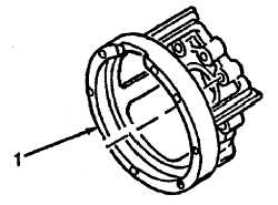
Repair end bell assembly as follows:
(a)
Coat any chipped area on end bell assembly (1) with red insulating enamel.
(b)
Place end bell assembly (1) in an oven for one hour at the temperature of 150F (66C). Remove and let
cool to ambient (room)temperature.
Figure 4-12. End Bell Assembly Repair
Refer to Figure 4-13.
(3)
Repair armature (1) as follows:
(a)
Perform measurements A and B to obtain diameter of bearing journals on shaft (2). Replace armature if
diameter is not within 0.6691 to 0.6694 inches.
(b)
Perform measurement C to obtain diameter of commutator (3). Replace armature (1) if commutator
diameter is less than 1.960 inches.
(c)
Install armature (1) in a lathe and refinish commutator (3). Remove only the material necessary to clean
and true-up commutator surface. Replace armature if commutator diameter must be refinished to less than
1.960 inches.
NOTE
If capabilities (tools and facilities) exist, perform bar concentricity of commutator
on armature. If not, replace armature.
(d)
Place measuring tool on commutator bar (3) and rotate armature (1) slowly for one complete turn to obtain
bar concentricity. Bar concentricity must be within 0.0002 inch.
4-15
|

