|
| |
TM 10-4320-342-24
3-32.
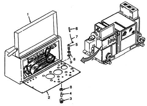
INDICATOR LIGHTS (ENGINE, ENGINE OIL TEMP AND CLUTCH DISENGAGED) REPLACEMENT
(TYPICAL).
NOTE
Heat shrink should be positioned one inch from wire end to avoid burning during
soldering.
(2)
Position new heat shrinks (6) on wire leads (7).
(3)
Strip and tin wire leads (7).
(4)
Install and solder wire leads (7) on indicator light (5).
(5)
Position new heat shrinks (6) over soldered connection and shrink. Remove tags from wire leads (7).
(6)
Install incandescent lamp (4) and lens cap (3) on indicator light (5).
(7)
Close and secure control panel (2).
(8)
Close and secure cover (1).
Figure 3-55. Indicator Lights (ENGINE, ENGINE OIL TEMP AND CLUTCH
DISENGAGED) Replacement (Typical)
3-118
|

