|
| |
TM 10-4320-324-14
NOTE
The main bearings are of thin-shell type. Their proper
installation requires that webs in crankcase be in
alinement and for bearing bores to be preloaded. No
attempt should be made to adjust or recondition bearing
shells.
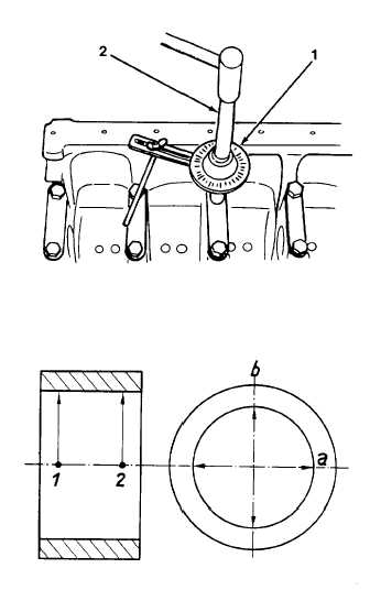
(4) Check preloading of bearing bores as follows:
(a) Position bearing caps, making sure that their
identification
numbers
match
with
those
stamped in crankcase. Torque bolts using
tightening fixture (1) and turning device (2) in
accordance instructions given in Appendix F,
Table F-1.
(b) Using a micrometer frame and precision gauge,
set gauge to 2.93 inches (74.5 mm).
(c) Measure each main bearing bore at points 1 and
2 in plane "a," then in the same manner in plane
"b" offset by 90 degrees, to determine any
contraction, out-of-roundness or conicity.
(d) If the recorded value is between 2.933 inches
(74.5 mm) and 2.934 inches (74.519 mm), the
respective bearing is in acceptable condition
and the required preload will be obtained when
bearing halves are installed.
(e) If the recorded bearing bore diameters differ only
slightly from the specified values given above,
repeat the measurements with new bearing
halves installed.
NOTE
Main bearings are made in two halves. No attempt may be made to recondition bearings.
(f) Insert new bearings.
(g) Position bearing cap, then preload and torque according to instructions given in Table F-1.
(h) Using a micrometer, adjust internal dial gauge set to nominal inside diameter of crankshaft main bearing bore,
2.7574 inches (70.04 mm).
6-47
|