|
| |
TM 10-4320-324-14
(g)
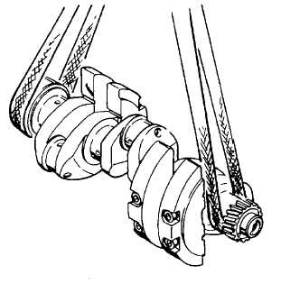
Using a micrometer, check other journals for out-of-round. Refer to Table 6-1 for tolerances.
(h)
Check working surface of radial packing ring on flywheel flange. Replace crankshaft if it is defective.
(27) Inspect camshaft for cracks and scores using the magnetic particle method. Replace if defective.
(28) Measure camshaft bearing journal outside diameter. Record journal diameter.
(29) Measure inside diameter of bearing. Subtract journal diameter from its bearing inside diameter. Replace
bearing if difference (clearance) is more than 0.0079 inch (0.20 mm).
(30) Inspect crankcase for cracks. Replace cracked crankcase.
(31) Check bearing housing for alinement as follows:
(a) Coat the main crankshaft journals
lightly with marking ink.
(b) Install crankshaft and bearing caps in
crankcase. Refer to Appendix F, Table
F-1 and torque bolts.
(c) Rotate crankshaft and then remove it.
If bearing bores are in alinement there
will be an even pattern on all bearing
bores.
CAUTION
The main bearings are of thin-shell type. Their proper installation requires that webs in crankcase be in
alinement and for bearing bores to be preloaded. No attempt should be made to adjust or recondition
bearing shells. Severe engine damage may result.
(32) Check preloading of bearing bores as follows:
(a)
Position bearing caps, making sure that their identification numbers match with those stamped in
crankcase. Torque bolts in accordance instructions given in Table 6-1.
(b)
Using a micrometer frame and precision gauge, set gauge to 2.93 inches (74.5 mm).
6-21
|