|
| |
TM10-4320-324-14
5-22. Cylinder Head Assembly Replacement.
This task covers:
a.
Removal
b.
Cleaning/Inspection
c.
Installation
d.
Follow-on Maintenance
INITIAL SETUP:
Tools
Equipment Condition
Tool kit, general mechanics, item 35, section III,
Muffler removed (para 4-28).
appendix B
Injection nozzle removed (para 5-15).
Torque wrench, item 34, section III, appendix B
Exhaust and intake manifold removed
Socket spanner, item 7, section III, appendix B
(para 5-18).
Socket spanner, item 8, section III, appendix B
Engine cowlings removed (para 5-19).
Spring compressor, item 26, section III,
V-belt guard removed (para 4-31).
appendix B
General Safety Instructions
Materials/Parts
Pushrod tube springs are under compression
Gasket - 415 7234
tension and can act as projectiles when
Intermediate ring - 223-0216
tension is released. Injury to personnel
Solder, item 14, appendix E
can result.
a.
Removal.
(1)
Raise cooling air compartment.
(1)
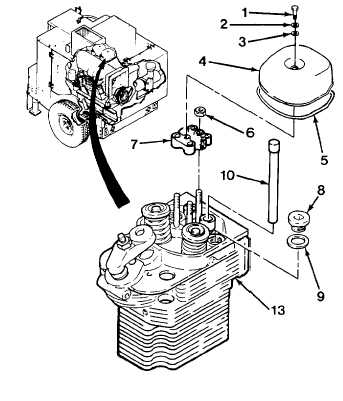
Remove bolt (1) and two flat washers (2
and 3).
(2)
Remove rocker cover (4) and gasket (5).
(3)
Remove three nuts (6), and rocker arm
assembly (7).
(4)
Remove two screw plugs (8) and two flat
washers (9), and two pushrods (10).
5-68
|