|
| |
TM 10-4320-324-14
Section III. TECHNICAL PRICIPLES OF OPERATION
1-18. Fuel System.
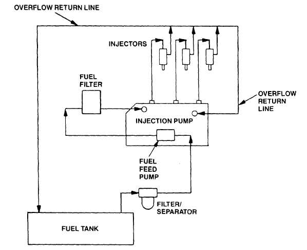
Figure 1-7. Fuel System Function Diagram
a.
Fuel Tank. Retained by hold down straps to trailer frame. Has 19 gallon (72 liters) capacity. Has fuel level gauge, fuel
source selector valve, filler cap, drain plug, and overflow return fitting.
b.
Filter/Separator. Attached to trailer frame. A throw-away element remove nearly 100% of water and solid contaminants
down to one micron in size.
c.
Fuel Feed Pump. A diaphragm type pump actuated by cam in fuel injection pump. Cleanable inlet screen. Provides
positive head of pressure to injection pump.
d.
Fuel Injector Pump. A high pressure fuel delivery pump driven by gear in engine timing cover. Main shaft in pump has
cams which operate plungers pumping fuel to injector nozzles. Controlled mechanically.
e.
Fuel Filter. A throw-away element removing contaminants from fuel on way to injection pump.
f.
Injector Nozzles. Single inlet, four outlet, high pressure injectors. Spray fuel directly into cylinders.
g.
Overflow Lines. Carry excess fuel not needed for combustion to fuel tank and injection pump.
1-12
|

