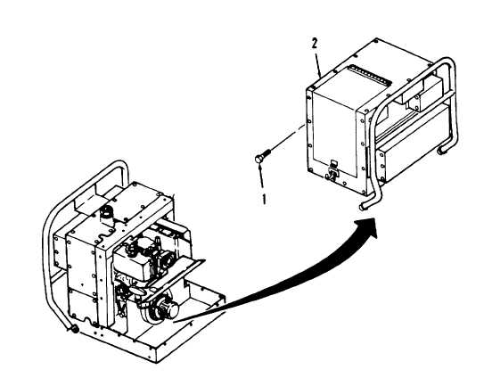
Order this information in Print

Order this information on CD-ROM

Download in PDF Format


Click here to make tpub.com your Home Page

Page Title: Figure 4-11. Enclosure Assembly, Inlet Side Removal.
Back | Up | Next

Click here for a printable version

Google


Web
www.tpub.com

Home


Information Categories
.... Administration
Advancement
Aerographer
Automotive
Aviation
Combat
Construction
Diving
Draftsman
Engineering
Electronics
Food and Cooking
Math
Medical
Music
Nuclear Fundamentals
Photography
Religion
USMC
   
Products
  Educational CD-ROM's
Printed Manuals
Downloadable Books


TM 10-4320-316-14 Figure 4-11.  Enclosure Assembly, Inlet Side Removal. b.  Disassembly.  (Refer to Figure 4-12). (1)  Drill out and remove four rivets (1) from door (2). (2)  Drill out and remove four rivets (1) and remove hinge (3). (3)  Drill out and remove two rivets (4) and two rivets (5). (4)  Remove catch strike (6) and clamping catch (7) from door (2). (5)  Drill out and remove ten rivets (8) and sheet (9) from sheet (10). (6)  Drill out and remove seven rivets (11) and sheet (12) from sheet (9). (7)  Drill out and remove eight rivets (13) and sheet (14) from sheet (9). (8)  If foam insulation is to be replaced, remove foam insulation as required. 4-39

Privacy Statement - Press Release - Copyright Information. - Contact Us - Support Integrated Publishing

Integrated Publishing, Inc. - A (SDVOSB) Service Disabled Veteran Owned Small Business