|
| |
TM 10-4320-316-14
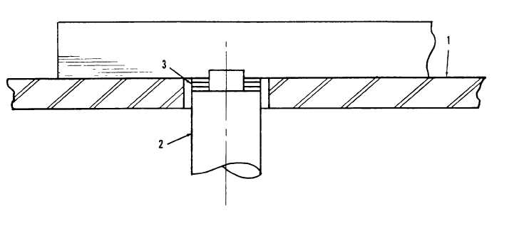
Figure 4-18. Measuring Impeller Clearance.
(b) (Refer to Figure 4-18. ) Position a straight edge across the surface of the wear plate (13) and install single .
010 shims onto shoulder of adapter shaft until the straight edge comes into contact with the edge of a shim when the
straight edge is slid across the wear plate surface and against the adapter shaft.
(c) Remove one .010 shim and replace with one .005 shim and repeat Step (b). If straight edge does not touch
the edge of the .005 shim, remove the .005 shim and install two .010 shims. This will provide a clearance of about .015
in. If the straight edge does touch the edge of the .005 shim, remove .005 shim and replace it with one .010 shim. This
will provide about .010 clearance.
(d) When clearance is correct, remove screw (1), washer (10), and lock washer (9). Then install impeller (11),
washer (10), new lock washer (9), and screw (8).
(8)
Install peeler (7) into pump.
(9)
Install plastic washer (6), set screw (5), and nut (4).
(10) Adjust the peeler by performing the following steps.
4-57
|