|
| |
TM 10-4320-311-14
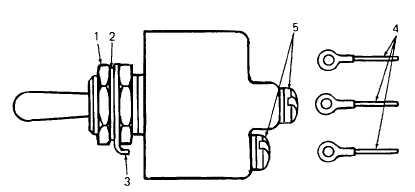
Figure 4-12. Toggle Switch
INSTALLATION:
a. Secure wire leads (4) to proper toggle switch terminals using screws (5).
b. Position toggle switch in panel and secure with locking ring (3), washer (2), and nut (1)
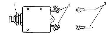
Figure 4-13. Circuit Breaker
INSPECTION. Refer to Figure 4-13.
Inspect the heater control circuit breakers for damage. Replace if damaged
REMOVAL:
a.
Remove outer nut (1) from circuit breaker.
b.
Remove circuit breaker from panel.
c.
Observe and tag the locations of wire leads (2).
d.
Remove wire leads (2) from circuit breaker by removing screws (3)
INSTALLATION:
a.
Secure wire leads (2) to proper circuit breaker terminals using screws (3)
b.
Position circuit breaker in panel and secure with nut (1).
INSPECTION: Refer to Figure 4-14.
Inspect the terminal block, located at the lower right rear of the frame below the intervehicie connector, for
damage. Replace if damaged.
4-29
|