|
| |
TM 5-4320-308-13
4-17.
INSPECT/REPLACE CYLINDER HEAD AND VALVE ASSEMBLY (Continued)
9 Adjust tappet clearance and decompression mechanism.
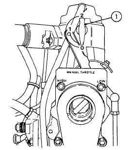
a. Put decompression lever (1) in position 0.
b. Turn engine clockwise when facing throttle control lever until compression resistance can be felt.
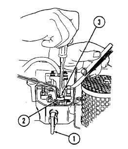
c. Check clearance between rocker and valve stem with a feeler gage. Tappet clearance cold should be
0.004 inch (0.10 mm). To correct clearance loosen nut (2).
d. Adjust screw (3) with screwdriver until feeler gage can be pulled between rocker and valve stem with very
slight resistance after nut (2) has been tightened.
10.
The adjustment of decompression adjustment screw (3) is required if the engine does not decompress when the
decompression lever is in position 1.
a. Turn engine in same direction as for adjusting tappet clearance.
b. Put decompression lever in position 1.
4-46
|