Order this information in Print

Order this information on CD-ROM

Download in PDF Format


Click here to make tpub.com your Home Page

Page Title: INSPECT/REPLACE CYLINDER HEAD AND VALVE ASSEMBLY (Continued)
Back | Up | Next

Click here for a printable version

Google


Web
www.tpub.com

Home


Information Categories
.... Administration
Advancement
Aerographer
Automotive
Aviation
Combat
Construction
Diving
Draftsman
Engineering
Electronics
Food and Cooking
Math
Medical
Music
Nuclear Fundamentals
Photography
Religion
USMC
   
Products
  Educational CD-ROM's
Printed Manuals
Downloadable Books


TM 5-4320-308-13 4-17. INSPECT/REPLACE CYLINDER HEAD AND VALVE ASSEMBLY (Continued) 
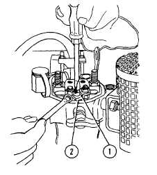
c.    Loosen nut (2) using box wrench 618 306 00 and turn adjustment screw (1) clockwise until rocker touches valve stem d.    Turn adjustment screw (1) another half turn and secure by tightening nut (2) 
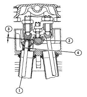
11.    Check clearance of complete pushrod (1) and pinion (2). a.    Use  a  feeler  gage  to  check  that  clearance  (3)  between  socket  of  complete  pushrod  (1)  and  pinion  (2)  is 0.039 inch (1.0 mm) b.    Check that clearance (4) is 0.039 inch (1.0 mm) c.    Clearances can be adjusted by adjusting complete pushrod (1) for clearance (3) and adjusting rocker shaft for clearance (4) NOTE During    engine    operation    decompression    shaft    must    not    move.        Assured clearances will prevent movement. 4-47

Privacy Statement - Press Release - Copyright Information. - Contact Us - Support Integrated Publishing

Integrated Publishing, Inc. - A (SDVOSB) Service Disabled Veteran Owned Small Business