|
| |
TM 5-4320-308-13
4-17.
INSPECT/REPLACE CYLINDER HEAD AND VALVE ASSEMBLY (Continued)
5
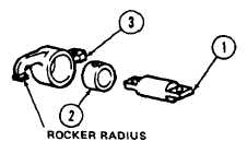
Measure rocker shaft (1) diameter. If rocker shaft
diameter is smaller than 0.7074 inch (17. 967 mm),
it must be replaced.
6
Measure rocker bore bushing (2) inside diameter. If
rocker bore bushing inside diameter is greater than
0.7076 inch (17.974 mm), replace bushing (2).
7
Measure rocker (3) radius. The radius must be 0. 315 inch (8 mm). No flattening or brinelling is permitted on
the
rocker radius. If there is any evidence of flattening the rocker must be replaced.
NOTE
When replacing rocker (3) you must also replace bushing (2). They are replaced as an assembly.
Bushing (2), however, can be replaced separately.
8
Inspect valve seats in cylinder head. If there is any evidence of damage, replace cylinder head.
9
Inspect valves. If there is any evidence of damage or distortion, replace valve.
ASSEMBLY/ADJUSTMENT:
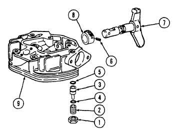
1
Install pinion (8) in cylinder head (9).
2
Insert decompression shaft (7) through cylinder head
(9) and into pinion (8).
3
Align holes in pinion (8) and decompression shaft
(7).
4
Install pin (6).
5
Install new preformed packing (5) on pin (3).
6
Install 10 spring plates (4) on pin (3). The spring
plates (4) must be installed in five sets with concave
sides together to create a spring action.
7
Install pin (3) with assembled preformed packing (5) and spring plates (4) into cylinder head (9).
8
Rotate decompression shaft (7) to horizontal position.
9
Install threaded pin (2) and tighten until snug.
10
Secure nut (1).
4-42
|