|
| |
TM 5-4320-308-13
4-17.
INSPECT/REPLACE CYLINDER HEAD AND VALVE ASSEMBLY (Continued)
CAUTION
Do not scratch the cylinder head sealing
face. Scratches could cause poor
sealing of cylinder head and cylinder.
11
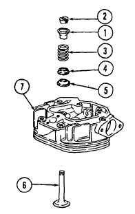
Insert valve (6) into cylinder head (7).
12
Install cap (5), washer (4), valve spring (3), and cup
(1).
13
Press down on cup (1) and install collets (2).
INSTALLATION/ADJUSTMENT:
CAUTION
Too small a clearance will damage
piston, cylinder head, and valves. Too
large a clearance will result in difficult
starting.
1
Adjust cylinder head clearance.
a.
Insert dial gage 612 087 00 into measuring
device 603 114 00.
b.
Put dial gage 612 087 00 with measuring device
603 114 00 on a flat surface.
c.
Pre-tension dial gage 612 087 00 (1) to 1 mm
and lightly tighten in position.
d.
Set the dial gage to zero.
e.
Install retaining bracket 612 752 00 (3) to retain
cylinder (4).
f.
Bring the piston to TDC position.
g.
Carefully lower dial gage 612 087 00 (1) with
measuring device 603 114 00 (2) on cylinder (4).
h.
Measure the distance between the top of the
cylinder and the top of the piston. Record
reading on dial gage (1).
4-43
|