|
| |
TM 5-4320-306-24
4-13.
REPLACE/REPAIR CRANKCASE ASSEMBLY (Continued)
21
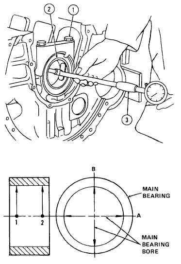
Check main bearing bore
a.
If a main bearing cap bore is within or
just slightly outside tolerance limits or if
a new main bearing cap is being used,
loosen bolts (1) alternately and evenly
far enough to be able to install main
bearings (2). Make sure matchmarks
are correctly alined if new bearings are
not being installed. Make sure oil
passage is installed in upper bearing
cap. If new caps or bearings are being
installed, match-mark them. Tighten
and retighten bolts as in step 20b.
b.
Measure
main
bearing
bore
with
micrometer (3) at points 1 and 2 and
along axes A and B. Bore should
measure
2.8757
to
2.8772
inches
(73.042 to 73.081 mm). If measurement
is not within these tolerance limits, main
bearing must be replaced.
c.
If measurements were taken with new
main bearings and a main bearing cap
that was only slightly outside tolerance
limits, the acceptable main bearing
tolerance limits may be increased to
2.8749 to 2.878 inches (73.022 to
73.101 mm). If measurements are still
not within these extended tolerance
limits, the main bearing caps and
crankcase must be replaced.
22
Check radial clearance.
a
Replacement of main bearings depends on the diameter of the crankshaft center bearing journal. Measure
diameter and determine radial clearance by subtracting journal diameter from bearing bore. Clearance
should be 0.0020 to 0.0043 inch (0.052 to 0.110 mm). Maximum allowable clearance is 0.0118 inch (0 3
mm),
b.
If radial clearance is not within these tolerance limits, recheck main bearings, main bearing cap, and/or
crankshaft. Replace components in that order until clearance is within tolerance limits.
23
Check side clearance.
a.
Measure width of crankshaft center bearing journal. Measure width of main bearing cap at bearing bore.
Determine side clearance by subtracting bearing cap width from bearing journal width. Side clearance
should be 0.0059 to 0.0124 inch (0.150 to 0.314 mm) Maximum allowable clearance is 0.0157 inch (0.4
mm).
b.
If side clearance is not within these tolerance limits, recheck main bearing cap and crankshaft center
bearing journal. Replace in that order until side clearance is within tolerance limits
4-112
|