|
| |
TM 5-4320-306-24
4-13
REPLACE/REPAIR CRANKCASE ASSEMBLY (Continued)
20
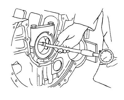
Check main bearing cap bore
a
Assemble upper and lower bearing caps, dowel bushings, washers, and bolts to crankcase. Make sure
matchmarks line up properly. Make sure threads and seat areas are clean. Lightly lubricate them with
lubricating oil
b.
Tighten bolts alternately and evenly, in small increments, to 22.13 ft-lb (30 N-m) torque. Using torque
gage No. 101910, tighten bolts an additional 60 degrees. Again tighten all screws 30 degrees.
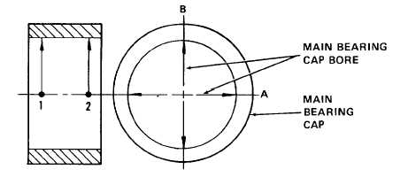
c.
Measure bore with a micrometer at points 1 and 2 and along axes A and B. Bore should measure 3.0512
to 3.0519 inches (77.50 to 77.519 mm). If all measurements are not within these tolerance limits, it may
be necessary to replace the bearing caps and crankcase. The crankcase and caps may be usable if the
cap bore is only slightly out of tolerance, but the bearing bore is within tolerance. Install new main bearings
and measure internal bearing bore. If the bearing bore is within tolerance, the caps and crankcase can be
used with these bearings, otherwise replace the crankcase and caps.
4-111
|