 |
|||
|
|
|||
|
|
|||
| ||||||||||
|
|
 TM 5-4320-273-14
the engine to operate at the governed speed.
pressure must be 4 to 5 pounds per square inch. When
the oil is cold, pressure will be higher.
c. Starter Switch. The starter switch (5) when
pressed permits current to flow from the battery to
k. Low Oil Pressure Safety Switch. The low oil
the starting motor to crank the engine for starting.
pressure safety switch plunger (7) stops the engine by
closing the ground circuit to the magneto when the
d. Ignition Switch. The ignition switch (6) controls
lubricating oil pressure falls below 1 pound per
the ignition circuit. When in the ON position, it per-
mits a high-tension current to be transmitted from
square inch. It must be manually set each time the
engine is started.
the magneto to the spark plugs. When in the OFF
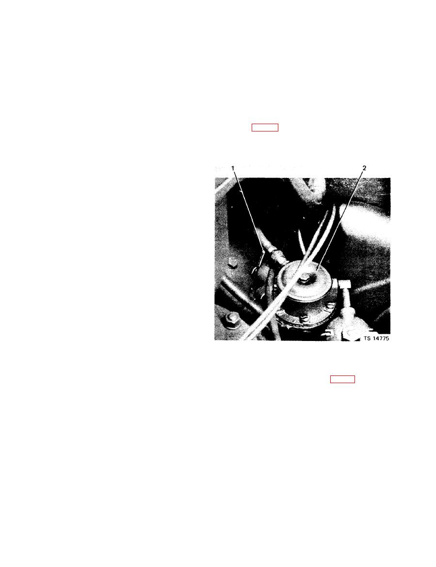
1. Fuel Hand Primer Lever. The fuel hand primer
position, it shorts out the magneto coil and stops the
lever (1, fig. 2-2) is operated in a back-and-forth
engine.
motion to pump fuel to prime the fuel lines at initial
e. Ammeter. The ammeter (3) indicates if the bat-
starting or after the engine has been idle for an ex-
tery is being charged or discharged while the engine
tended period of time.
is in operation. The ammeter should show a high
charge rate to restore battery energy immediately af-
ter starting and then taper off to zero with continued
operation.
hourmeter (8) registers the rpm of the engine and
maintains a running total of the engine operating
hours and tenths of hours.
g. Engine Vacuum Gage. The engine vacuum gage
(10) is a measure of the engine horsepower output.
The horsepower required to drive the pump varies
with the weight of the liquid being pumped and the
capacity or rate of pumping. For example, jet fuel
having a specific gravity of 0.8 requires only eight-
tenths as much horsepower at a given flow rate as
does water having a specific gravity of LO. The
vacuum reading on the engine vacuum gage is in-
dicative of the horsepower being generated - the
higher the vacuum, the less the horsepower.
h. Pump Suction Gage. The pump suction gage (11)
indcates either a vacuum or pressure at the pump
inlet, depending on pump application.
i. Pump Discharge Pressure Cage. The pump
1. Hand primer lever
pressure gage (9) indicates discharge pressure at the
2. Fuel pump
pump outlet.
2-2. Fuel hand
Figure
primer lever.
j. Oil Pressure Cage. The oil pressure gage (4) in-
dicates the oil pressure within the lubricating
The fuel gage (6, fig. 2-3) indicates
m. Fuel Cage.
system. At normal operating temperature, the oil
the level of fuel in the fuel tank.
|
|
Privacy Statement - Press Release - Copyright Information. - Contact Us |
