 |
|||
|
|
|||
|
Page Title:
Figure 4-7. Manifold and carburetor, exploded view. |
|
||
| ||||||||||
|
|
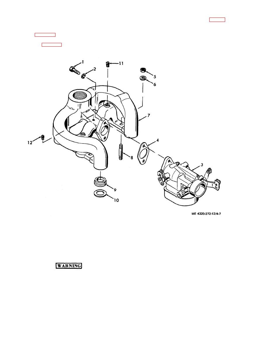 (5) Remove the two cap screws (1, fig. 4-7)
(2) Disconnect the choke control wire from
and lock washers (2) that secure the carburetor to
the carburetor choke lever.
(3) Disconnect the fuel line from the car-
the manifold; remove the carburetor (3) and gasket
(4).
buretor (para 4-18 a).
(4) Disconnect the air cleaner hose from the
carburetor (para 4-17 a).
1. Cap screw
7. Manifold
2. Lock washer
8. Stud
3. Carburetor
9. Insert
4. Gasket
10. Gasket
5. Nut
11. Pipe plug
6. Flat washer
12. Pipe plug
c. Cleaning and Inspection
(2) Inspect the carburetor for cracks and
other obvious damage. Check the operation of the
throttle lever and choke lever. They must operate
Clean all parts in a well-ventilated area.
freely, without binding. Replace the carburetor if
Avoid inhalation of solvent fumes and
you determine that it is defective.
prolonged exposure of the skin to
d. Installation. Install the carburetor by
cleaning solvent. Wash exposed skin
reversing the r e m o v a l procedure. N o t e t h e
thoroughly.
following:
(1) Clean the exterior of the carburetor with a
(1) Make sure there are no air leaks between
cloth dampened with cleaning solvent (fed. spec. P-
the carburetor and air cleaner. Air leaks will allow
D-680); dry thoroughly.
|
|
Privacy Statement - Press Release - Copyright Information. - Contact Us |
