 |
|||
|
|
|||
|
Page Title:
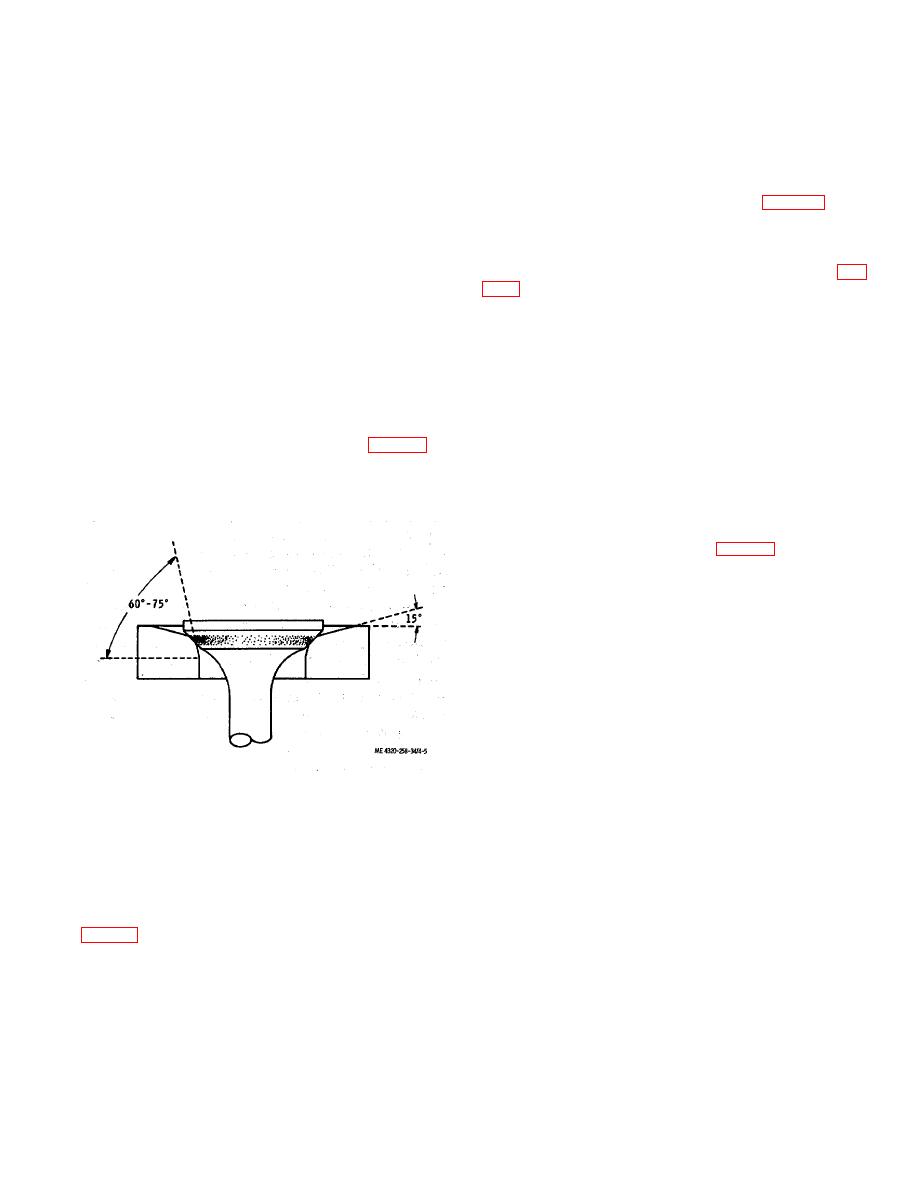
Figure 4-5. Narrowing valve seat. |
|
||
| ||||||||||
|
|
 TM 5-4320-258-34
Length
Load (minimum)
valve is installed in the guide from which it was
1-45 / 64 inches (closed)
42 pounds
removed.
1-27 / 64 inches (open)
86 pounds
(3) With the engine stopped, temporarily
set the intake-valve-to-tappet clearance to 0.014 inch
(9) Grind the valve seats. The seat angle
and the exhaust valve-to-tappet clearance to 0.017 inch
of the intake valves is 30. The seat angle of the
(cold).
exhaust valve is 45. Use a dial indicator to check the
(4) Install the cylinder head (para 4-3).
valve seat for runout. The total indicator reading must
(5) Operate the engine until it reaches
not exceed 0.002 inch. Clean the valve seat and
operating temperature. Adjust valve tappet clearance
as directed in subparagraph e below.
surrounding area thoroughly after grinding.
(10) After the valves and seats have been
(6) Install the valve chamber cover (7, fig.
refaced and reground, coat the seat lightly with Prussian
e. Valve Adjustment.
blue 'and drop the valve into place, oscillating it slightly
to transfer the blue pattern to the valve face. This
(1) Operate engine until it reaches
should show a contact width of 1/ 16 to 3/ 32 inch, and
operating temperature.
should fall well within the width of the valve face,
(2) Disconnect the positive crankcase
leaving at least 1 / 64 inch on either side of the contact
ventilation valve and fittings from the valve chamber
area. If the contact area is greater than 3 / 32 inch,
cover.
narrow the contact area by grinding the outside diameter
(3) Remove the nuts and washers that
of the seal with a 15 stone or by grinding the inside
secure the valve chamber cover to the cylinder block.
diameter of the seat with a 60 or 75 stone (fig. 4-5).
Remove the valve chamber cover and gasket.
After the seat area is corrected, touch the seat lightly
(4) With the engine at operating
with the original grinding stone to remove the burred or
temperature: and running at idle speed, set the intake
feathered edge.
valves for; 0.014-inch clearance as follows:
(a) Alternately pass a 0.013-inch and
a 0.015-inch flat feeler gage between the head of the
adjusting screw of the tappet (13, fig. 4-3) and stem of
valve (2).
(b) If a 0.013-inch feeler gage moves
freely back and forth in gap when the valve is not being
lifted and 0.015-inch feeler gage binds at all times, the
clearance requires no adjustment.
(c) If a 0.013-inch feeler gage is
gripped at all times, the clearance is insufficient.
(d) Hold valve lifter with an open end
wrench while using a second wrench to turn adjusting
screw one-quarter to one-half turn clockwise. Repeat
clearance check and adjustment until proper clearance
is obtained. The adjustable-type valve lifters have self-
locking adjusting screws that require no lock nuts.
(e) If 0.015-inch feeler gage moves
Figure 4-5. Narrowing valve seat.
freely when valve is not being lifted, the clearance is too
great. 'Hold valve lifter with an open end wrench while
(11) Inspect the spring retainer seats,
using a second wrench to turn valve lifter adjusting
spring retaining locks, valve stem caps, and valve
screw counterclockwise one-quarter to one-half turn.
tappet assemblies for cracks, scoring, overheating, and
Repeat the clearance check, and adjustment until proper
wear. Replace damaged parts.
clearance is obtained.
d. Installation.
(5) Adjust the exhaust valves to a 0.016
(1) Position the valve tappet assemblies
(hot) clearance in the manner described above, using
(13, fig. 4-3) in the engine block.
0.015and 0.017-inch feeler gage.
(2) Assemble-the valves (2 and 7), valve
4-5.
Intake and Exhaust Manifolds
springs (5 and 10), spring retainers (4 and 9), valve
a. Removal and Disassembly.
rotators (3 and 8), and valve locks (1 and 6). Compress
(1) Remove the carburetor from the intake
the valve springs with a spring compressor to install the
manifold (TM 5-4320-258-12).
valve locks. Turn the engine over as necessary to allow
each valve to move to the closed position before
attempting to install the valve parts. Make sure each
4-9
|
|
Privacy Statement - Press Release - Copyright Information. - Contact Us |
