 |
|||
|
|
|||
|
|
|||
| ||||||||||
|
|
 b.
Removal and disassembly
1. Remove the two cap screws securing the control panel bracket to the intermediate housing.
2. Disconnect electrical connector by turning its sleeve counterclockwise.
3. Refer to Fig. 3-5 and disassemble the control panel as necessary to replace the defective parts.
c.
Cleaning and Inspection
1.
Clean all parts with an approved cleaning solvent. Dry thoroughly.
2.
Inspect for damaged wire insulation, and worn, burnt, or loose terminals.
3.
Check switches for proper continuity.
4.
Check gages for cracked dial glass, discolored or illegible dials, or other damage.
5.
Repair or replace damaged parts. NOTE: Wiring harness is serviced as an assembly.
d.
Reassembly and Installation
1. The reassembly and installation proceedure is the reverse of the removal and disassembly proceedure.
B. ELECTRICAL SENDING UNIT
a.
General - The electrical sender constantly monitors
the engine speed and sends electrical impulses to the
tachometer mounted on the control panel. NOTE: The terminal
on the sending unit cover screw is for a ground wire, which is not
necessary in this installation because the sending unit grounds
itself.
b.
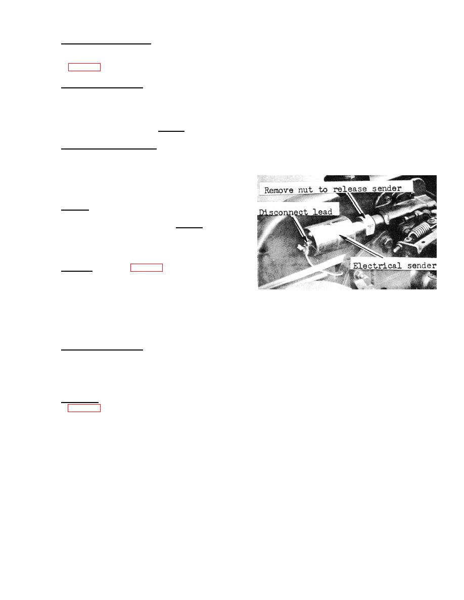
Removal - Refer to Fig. 3-6 and remove the electrical
sending unit.
FIGURE 3-6. ELECTRICAL SENDING UNIT
c.
Cleaning and Inspection
1.
Clean the sending unit with an approved cleaning solvent. Dry thoroughly.'
2.
Inspect for cracks, breaks, defective insulation, and other damage.
3.
Manually turn the shaft of the sender. It should rotate easily, without binding or catching.
4.
Replace a damaged sender.
d.
Installation
1.
Refer to Fig. 3-6.
2.
Insert squared end of the drive tip into the sending unit.
3.
Mount the sending unit on the tachometer drive and tighten nut.
4.
Connect the terminal to the center of the sending unit cover.
17
|
|
Privacy Statement - Press Release - Copyright Information. - Contact Us |
