 |
|||
|
|
|||
|
|
|||
| ||||||||||
|
|
 (2) Inspect for broken or damaged wire insulation;
engine in the RUN position and to interrupt spark in
the STOP position. The OIL switch, when released,
worn, burned, or loose terminals, and cracked,
completes a connection to the oil pressure gage to
broken, or damaged parts.
provide an indication of engine oil pressure. The
(3) Check switches for proper continuity. Refer to
START switch, when depressed, completes a con-
nection to the engine starter to turn over the engine.
b . Tachometer and Sender. Engine speed is con-
(4) Check the tachometer and oil pressure gage for
stantly monitored by the electrical sending unit,
cracked dial glasses, discolored or illegible
dials, or other damage.
which is mounted on the engine governor, and which
sends electrical impulses to the tachometer mounted
(5) Repair or replace damaged parts.
on the control panel. The tachometer provides an
i n d i c a t i o n of engine speed in rpm's.
c. Reassembly and Installation.
c . Battery. T h e battery supplies the electrical
(1) Refer to figures 3-5 and 1-3 and reassemble
power necessary to operate the starter to start the
the control panel.
engine. It is a 24-volt, lead-acid type, and it is
mounted in a covered battery box which is secured
(2) Refer to figure 3-4 and install the control panel.
to the skid base. The negative battery terminal is
connected to the frame with a ground strap. The
3-13. ELECTRICAL SENDING UNIT
positive battery terminal connects to a terminal on
the starter by means of a battery cable.
a. Removal. Refer to figure 3-6 and remove the
electrical sending unit.
3-12. CONTROL PANEL
b. Cleaning and Inspection.
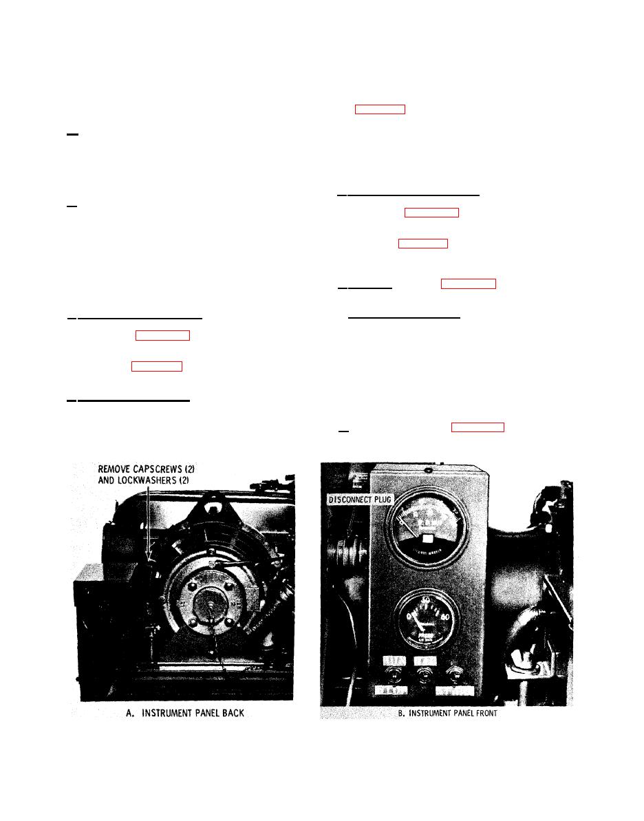
a. Removal and Disassembly.
--
(1) Refer to figure 3-4 and remove the control
(1) Clean sending unit with a cloth dampened lightly
with an approved cleaning solvent; dry thoroughly.
panel.
(2) Inspect sending unit for cracks, breaks, defec -
(2) Refer to figure 3-5 and disassemble the control
tive insulation, and other damage. Manually turn
panel as necessary to replace defective parts.
the shaft of the sender. It should rotate easily
without catching or binding. Replace a damaged
b. Cleaning and Inspection.
sender.
(1) Clean all electrical parts with a cloth lightly
c . Installation. Refer to figure 3-6 and install the
dampened with an approved cleaning solvent;
electrical sending unit.
dry thoroughly.
|
|
Privacy Statement - Press Release - Copyright Information. - Contact Us |
