 |
|||
|
|
|||
|
Page Title:
Section XVIII. CONNECTING RODS, CONNECTING ROD BEARINGS, PISTONS, FILLER BLOCK, MAIN BEARING CAPS, MAIN BEARINGS, CRANKSHAFT,... |
|
||
| ||||||||||
|
|
 TM 5-4320-243-15
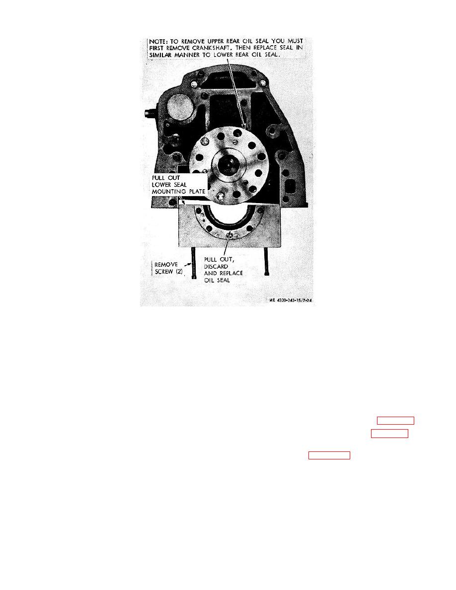
Figure 7-24. Rear oil seal, removal and installation.
BEARING CAPS, MAIN BEARINGS, CRANKSHAFT, CRANKSHAFT GEAR, AND CAMSHAFT BUSHINGS
7-53. General
control crankshaft endplay. The crankshaft gear is
The connecting rods, made of drop-forged steel, are
mounted on the front of the crankshaft and drives the
precision machined at each end. The pistons are made
camshaft gear.
of aluminum alloy and are both tapered and oval
ground. Grooves for 3 compression rings and 1 oil-
7-54. Connecting Rods, Pistons, and Piston Pins
control ring are machined into each piston above the
a. Remove and install the cylinder heads (para 7-
piston pin bore. The filler block is located at the lower
37).
rear of the cylinder assembly and must be removed for
crankshaft removal. The crankshaft is a 1-piece steel,
case hardened forging, counter balance with 12 integral
counterweights. Seven main bearings caps support the
d. Remove and install the connecting rods and
crankshaft in the cylinder assembly. The crankshaft
pistons as shown by figure 7-25.
rides in 7 upper-half and 7 lower-half main bearings.
Both halves of the center main bearing are flanged to
7-29
|
|
Privacy Statement - Press Release - Copyright Information. - Contact Us |
