 |
|||
|
|
|||
|
Page Title:
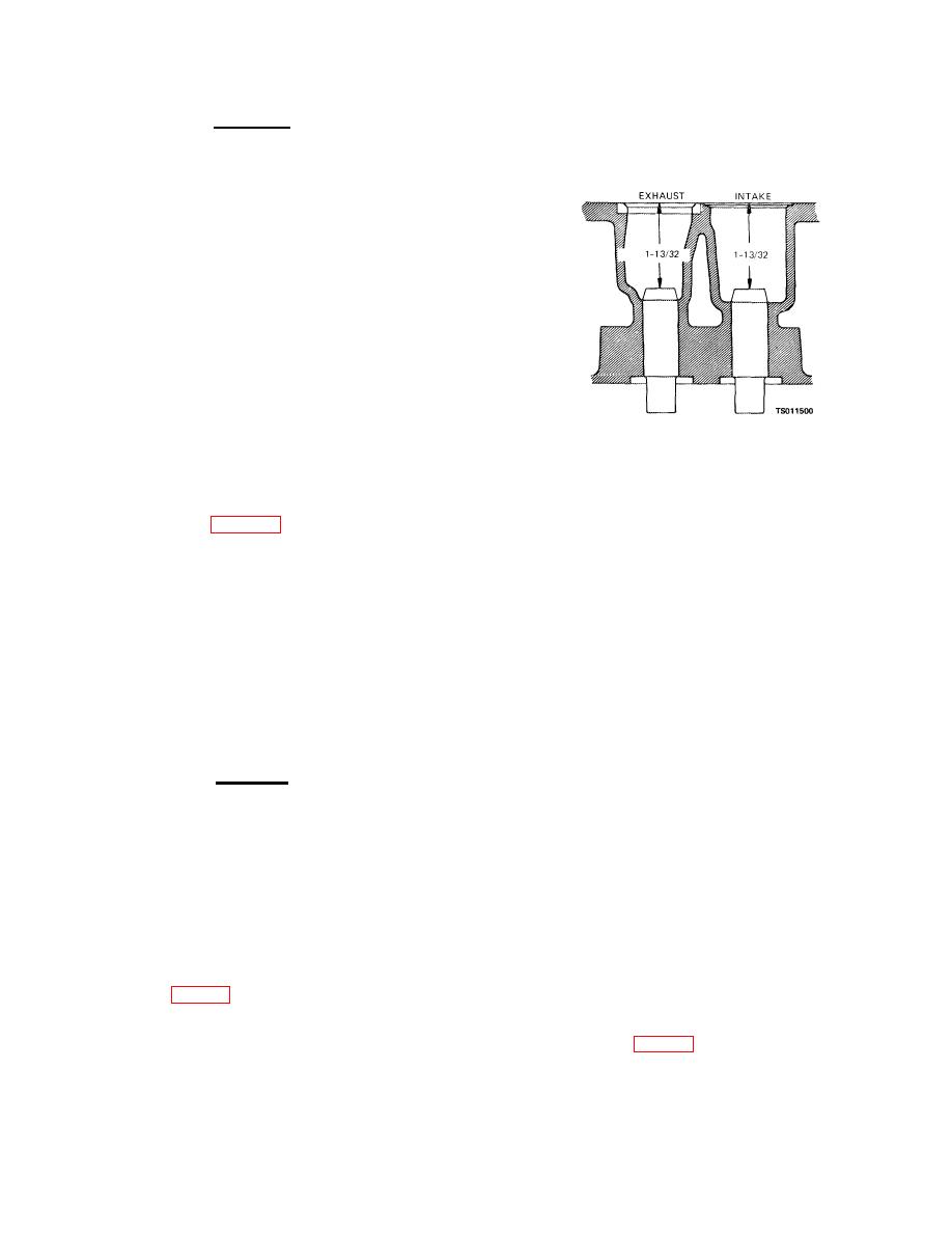
Figure 4-4. Valve guide installation dimensions. |
|
||
| ||||||||||
|
|
 TM 5-4320-234-34
c. Cleaning, Inspection, and Repair.
the original valve seats to a diameter of 1.3535 to
1.3545 inches (3.3837 to 3.3862 cm). This will provide
WARNING
the required press fit.
If valve seats had been
Clean all parts in a well-ventilated
counterbored previously, rebore to 0.01 inch (0.0250
area. Avoid inhalation of solvent
cm)
fumes and prolonged exposure of
skin to cleaning solvent. Wash
exposed skin thoroughly.
Dry
cleaning solvent (Fed. Spec. P-D-
680) used to clean parts is
potentially
dangerous
to
personnel and property. Do not
use near open flame or excessive
heat. Flash point of solvent is 100
F. to 138 F. (38 C. to 59 C. ).
(1) Clean the valves, valve springs, and
valve tappet assemblies with cleaning solvent (Fed.
Spec.
P-D680); dry thoroughly.
Remove carbon
deposits with a wire brush.
(2) Clean the valve guides installed in the
Figure 4-4. Valve guide installation dimensions.
block with a valve guide cleaner or wire brush. Remove
oversize to provide a 0.003 to 0.005 inch (0.0075 to 0.
all lacquer and other deposits.
0125 cm) press fit. Counterbore deeply enough so that
(3) Clean the valve seats with a wire brush.
the boring tool will clean up the bottom of the bore to
(4) Inspect the valves for cracks, bent stems,
ensure proper heat conduction from the valve insert.
distortion, and wear (table 4-1). If the valves are not
Chill the valve seats in dry ice for 20 minutes. Install
seriously damaged, regrind them. After grinding, the
the valve seat in place with a piloted driver, by using an
valve head thickness must be at least 50 percent of a
arbor press or by applying light blows with a hammer
new valve's thickness. You must replace the valves if
until the valve seat is resting against the bottom of the
they are ground to less than this amount. Check the
bore. Roll or peen the valve seat into place.
reground valves on V-blocks with an indicator. The
(8) Check the valve springs for cracks and
contact face must be true with the stem to within 0.002
distortion. Test compression strength with a spring
inch (0.0050 cm).
tester. Compression strength must be as follows:
(5) Check for loose or worn valve guides.
Length
Load (minimum)
Check the internal diameter of the valve guide with a
1-45/64 inches (closed) (4.2577 cm)
42 pounds (18.90 kg)
telescope gage and a micrometer. Replace guides that
1-27/64 inches (open) (3.5547 cm)
86 pounds (38.70 kg)
are worn to a bell-mouthed shape or guides that have a
(9) Grind the valve seats. The seat angle of
maximum diameter of more than 0.3447 inch (0.8617
the intake valve is 30 The seat angle of the exhaust
.
cm).
valves is 45 Use a dial indicator to check the valve
.
CAUTION
seat for runout. The total indicator reading must not
Do not attempt to ream the valve
exceed 0.002 inch (0.0050 cm). Clean the valve seat
guides after seating them. Guides
and surrounding area thoroughly after grinding.
are pre-reamed and coated.
(10) After you have refaced and reground the
Further reaming will remove the
valves and seats, coat each seat lightly with Prussian
coating.
blue and drop the valve into place, oscillating it slightly
(6) If the valve guides are worn or damaged,
to transfer the blue pattern to the valve face. This
press out the guides from the combustion side, using a
should show a contact width of 1/16 to 3/32 inch (0.
driver that is slightly smaller than the external diameter
1562 to 0.2342 cm), and should fall well within the width
of the guide. With the driver, press in new guides from
of the valve face, leaving at least 1/64 inch on either
the combustion side. When properly seated, valve
side of the contact area. If the contact area is greater
guide tops will be 1-13/32 inches (3.5155 cm) from the
than 3/32 inch (0.2342 cm), narrow the contact area by
top of the block (fig. 4-4).
grinding the outside diameter of the seat with a 15
(7) Check the exhaust valve seat inserts for
stone or by grinding the inside diameter of the seat with
cracks or loose mountings. Pull out faulty valve seat
a 60or 75stone (fig. 4-5). After the
inserts. Replace original valve seats with new 0.010
inch (0.0250 cm) oversized valve seats. Counterbore
4-7
|
|
Privacy Statement - Press Release - Copyright Information. - Contact Us |
