 |
|||
|
|
|||
|
Page Title:
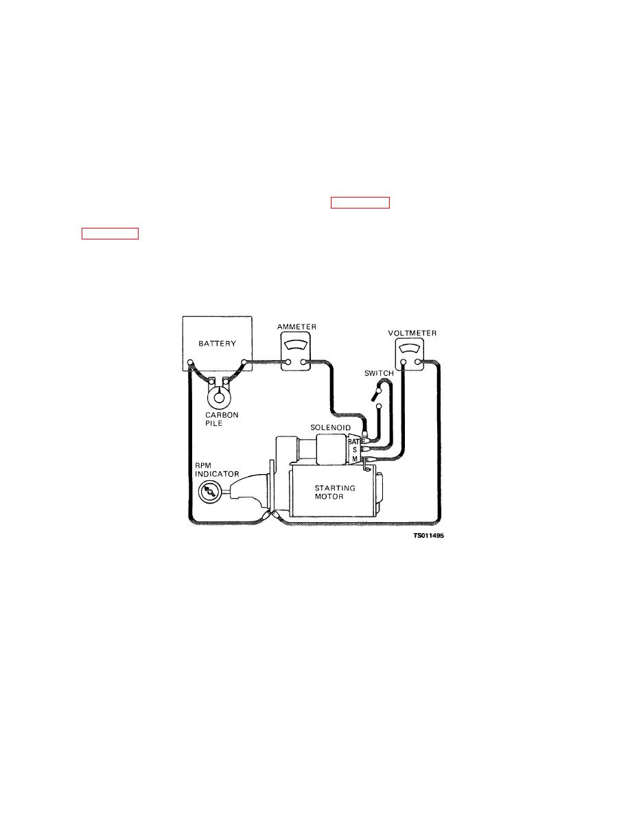
Figure 3-16. Starting motor no-load test setup. |
|
||
| ||||||||||
|
|
 TM 5-4320-234-34
(2) Remove the support pins (6) to release
NOTE
the grounded brush holders (10), insulated brush holders
Thecommutator on the armature shaft must be smooth and concentric,
(11), and brush springs (7) from the brush supports.
free from burrs, scoring, high segments, burned segments, or other
Remove the brush screws (8) that secure the brushes
damage. You should replace the starting motor if the commutator is
(9) to the brush holders; you can now remove the
damaged.
brushes.
(6) Install the commutator end frame (4) with
(3) Remove the screws (14), nuts (12), and
the through bolts (3).
washers (13) that secure the brush leads (15) to the
d. Testing. To perform a no-load test,
brush support; remove the brush leads.
connect the starting motor in series with a fully charged
(4) Replace the brushes if you find them
24-volt battery, an ammeter of 0to 500-ampere range
chipped, oil soaked, or worn to less than 5/16 inch
and a large variable carbon pile resistor as shown in
(0.7812 cm). Replace any other parts that are cracked,
worn, or distorted.
You will also need a tachometer to measure armature
(5) Install the brushes and related parts as
speed. Energize the starting motor and adjust the
shown in figure 3-15. Before installing the commutator
variable resistor until you have a reading of 20 volts.
end frame (4), seat the brushes on the commutator
Armature rotation should be within the range of 3300 to
using 00 sandpaper.
5600 rpm with a current draw between 40 and 75
amperes. Interpret the results as follows:
Figure 3-16. Starting motor no-load test setup.
(1) Current draw and no-load armature speed
commutator bars), or lack of continuity between brushes
within the above limits indicate normal condition of the
and commutator.
starting motor.
(5) Low free speed with low current draw
(2) Low free speed or high current draw
indicates high internal resistance due to poor
indicates too much friction, caused by damaged
connections, defective leads, or a dirty commutator.
bearings or a bent shaft, a shorted armature, or a
(6) High free speed with high current draw
grounded armature or field.
indicates a shorted field.
(3) No rotation with high current draw
e.
Disassembly. Disassemble the start
indicates a grounded field terminal or frozen bearings.
motor
(4) Failure to operate with no current draw in
dicates an open field circuit, open armature coils (this
condition is normally accompanied by badly burned
3-18
|
|
Privacy Statement - Press Release - Copyright Information. - Contact Us |
