 |
|||
|
|
|||
|
Page Title:
Table 2-1. Controls and Instruments |
|
||
| ||||||||||
|
|
 TM 5-4320-234-12
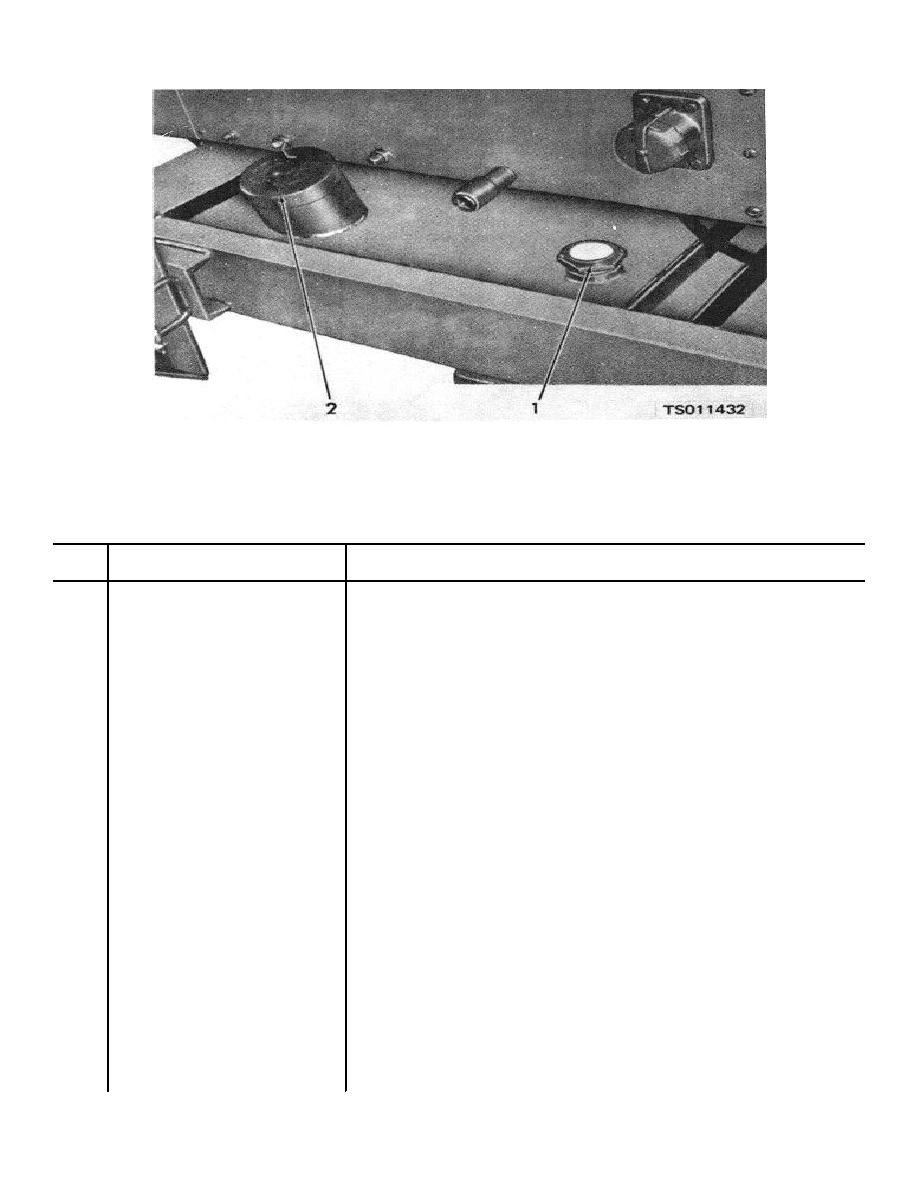
1. Fuel tank level gage
2. Fuel tank filler cap
Figure 2-3. Fuel tank and related parts.
Table 2-1. Controls and Instruments
Fig. &
index No.
Name
Operation and use
2-1 1
Engine oil pressure safety switch
Automatically shuts down the unit when engine oil pressure falls below preset
level of the switch. Correct cause of trouble before restarting operation.
2-1 2
Coolant temperature safety switch
Automatically shuts down the unit when engine coolant temperature increases
above preset setting of the switch. Correct cause of trouble before restarting
operation.
2-1 3
Indicates rate of battery charge or discharge. Charging rate may be higher
immediately after starting but should taper off to near zero with continued
operation. Immediately check cause of discharge indication that occurs during
operation.
2-1 4
Coolant temperature gage
Indicates the temperature of engine coolant during operation. Normal operating
temperature reading is 180 to 200F.
2-1 5
Throttle control
Controls engine speed between idle and governed speed. When pulled out, it
causes the engine to operate at idle speed. When pushed in fully, it causes
engine to run at full governed speed. Intermediate settings provide intermediate
engine speeds.
2-1 6
Control panel lamp
Provides illumination for control panel when operating during hours of darkness.
2-1 7
Engine oil pressure gage
Indicates engine oil pressure. At idle, oil pressure must exceed 7 psi. At
governed speed, oil pressure must be 20 to 30 psi.
2-1 8
Choke control
When pulled out, the choke control supplies an extra-rich fuel mixture to the
engine to facilitate engine starting and warmup. When pushed in fully, it
restores normal fuel mixture for running the engine.
2-1 9
Suction gage
Compound gage indicates either vacuum or pressure condition at suction port
when suction gage valve is open. Indication depends upon specific operating
conditions.
2-1 10
Tachometer-hourmeter
Indicates the engine speed in hundreds of rpms. Normal governed speed rating is
2450 rpm. Engine speed at full load should not go beyond this level..
Hourmeter indicates engine running time based on operating speed (engine
revolutions x 100,000).
2-1 11
Discharge pressure gage
Indicates pump discharge pressure when discharge pressure gage valve is open.
High pressure indicates high discharge head or discharge line restriction.
Normal discharge pressure varies with operating conditions.
2-1 12
Starter pushbutton
When the battery disconnect switch and ignition switch are ON, pressing the
starter pushbutton energizes the engine starting motor to turn over the engine
for starting.
2-4
|
|
Privacy Statement - Press Release - Copyright Information. - Contact Us |
