|
| |
TM 10-4930-250-13&P
1.9.2 LiquidFuelFilter-Separator.
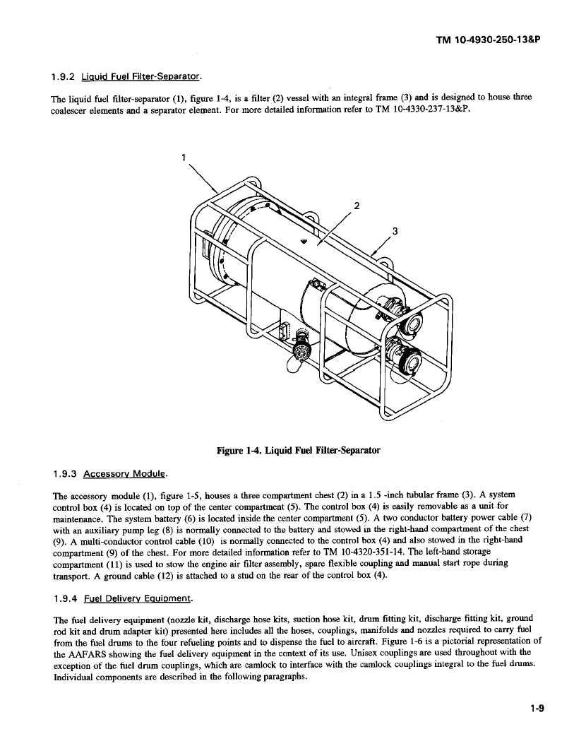
Theliquidfuelfilter-separator(1), figure1-4,is a filter (2)vesselwith anintegralframe(3) andis designedto housethree
coalescer elements and a separator element. For more detailed information refer to TM 10-4330-237-13&P.
2
3
Figure 1-4. Liquid Fuel Filter-Separator
1.9.3
Accessory
Module.
The accessory module (1), figure 1-5, houses a three compartment chest (2) in a 1.5 -inch tubular frame (3). A system
control box (4) is located on top of the center compartment (5). The control box (4) is easily removable as a unit for
maintenance. The system battery (6) is located inside the center compartment (5). A two conductor battery power cable (7)
with an auxiliary pump leg (8) is normally connected to the battery and stowed in the right-hand compartment of the chest
(9). A multi-conductor control cable (10) is normally connected to the control box (4) and also stowed in the right-hand
compartment (9) of the chest. For more detailed information refer to TM 10-4320-351-14. The left-hand storage
compartment (11) is used to stow the engine air filter assembly, spare flexible coupling and manual start rope during
transport. A ground cable (12) is attached to a stud on the rear of the control box (4).
1.9.4
Fuel Delivery Equipment.
The fuel delivery equipment (nozzle kit, discharge hose kits, suction hose kit, drum fitting kit, discharge fitting kit, ground
rod kit and drum adapter kit) presented here includes all the hoses, couplings, manifolds and nozzles required to carry fuel
from the fuel drums to the four refueling points and to dispense the fuel to aircraft. Figure 1-6 is a pictorial representation of
the AAFARS showing the fuel delivery equipment in the context of its use. Unisex couplings are used throughout with the
exception of the fuel drum couplings, which are camlock to interface with the camlock couplings integral to the fuel drums.
Individual components are described in the following paragraphs.
1-9
|