|
| |
TM 10-4930-250-13&P
1.9. LOCATION AND DESCRIPTION
OF MAJOR COMPONENTS.
The AAFARS, shown in it's normal configuration in figure 1-1, consists of the pump-engine module, the liquid fuel filter-
separator, the accessory module, the auxiliary pump module, fire extinguishers and the fuel delivery equipment (nozzle kit,
discharge hose kits, suction hose kit, drum fitting kit, discharge fitting kit, ground rod kit and drum adapter kit) required to
deliver fuel from fuel drums to four fueling points. An alternative configuration, figure 1-2, uses an additional 3-inch discharge
hose to allow an in-line setup. Use of the additional discharge hose will reduce flow to the farthest nozzle slightly below design
requirements.
1.9.1 Pump-Engine Module.
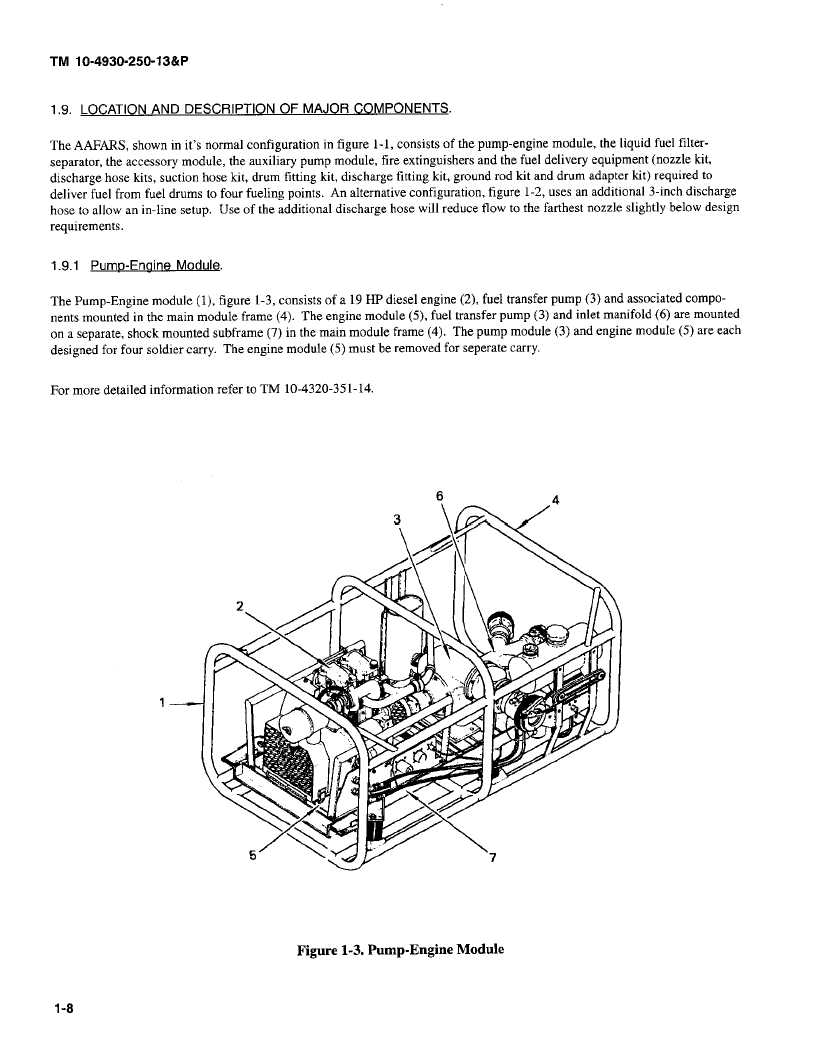
The Pump-Engine module (1), figure 1-3, consists of a 19 HP diesel engine (2), fuel transfer pump (3) and associated compo-
nents mounted in the main module frame (4). The engine module (5), fuel transfer pump (3) and inlet manifold (6) are mounted
on a separate, shock mounted subframe (7) in the main module frame (4). The pump module (3) and engine module (5) are each
designed for four soldier carry. The engine module (5) must be removed for seperate carry.
For more detailed information refer to TM 10-4320-351-14.
6
4
3
2
7
Figure
1-3. Pump-Engine
Module
1-8
|

