Order this information in Print

Order this information on CD-ROM

Download in PDF Format


Click here to make tpub.com your Home Page

Page Title: Figure 2-110. Winch Control Station
Back | Up | Next

Click here for a printable version

Google


Web
www.tpub.com

Home


Information Categories
.... Administration
Advancement
Aerographer
Automotive
Aviation
Combat
Construction
Diving
Draftsman
Engineering
Electronics
Food and Cooking
Math
Medical
Music
Nuclear Fundamentals
Photography
Religion
USMC
   
Products
  Educational CD-ROM's
Printed Manuals
Downloadable Books


TM 10-4320-342-24 2-81.  WINCH CONTROL BOX ASSEMBLY REPAIR - continued. b. 
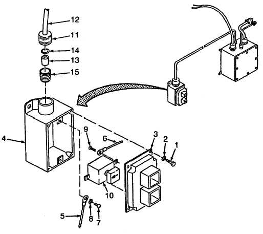
DISASSEMBLE.  Refer to Figure 2-110. (1)   Remove screws (1), flatwashers (2) and cover (3) from box (4). (2)   Tag electrical leads (5 and 6). (3)   Remove screw (7), lockwasher (8) and electrical lead (5) from box (4). (4)   Remove screws (9) and electrical leads (6) from switches (10). (5)   Unscrew seal nut (11) and remove cable (12) from box (4). (6)   Remove seal (13), seal ring (14) and seal nut (11) from cable (12). (7)   Remove adapter (15) from box (4). Figure 2-110.  Winch Control Station 2-252

Privacy Statement - Press Release - Copyright Information. - Contact Us - Support Integrated Publishing

Integrated Publishing, Inc. - A (SDVOSB) Service Disabled Veteran Owned Small Business