|
| |
TM 10-4320-342-24
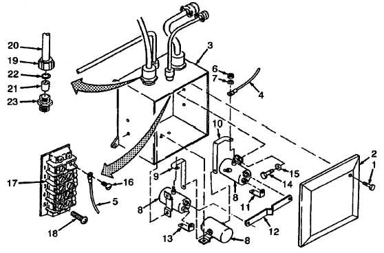
2-81. WINCH CONTROL BOX ASSEMBLY REPAIR - continued.
Refer to Figure 2-111.
(8)
Remove screws (1) and cover (2) from junction box (3).
(9)
Tag all electrical leads (4 and 5 typical).
NOTE
Note location and position of electrical and buss connectors prior to removal.
(10)
Remove nuts (6), lockwashers (7), electrical leads (4) and connectors (9, 10, 11, 12 and 13) from solenoid
valves (8).
(11)
Remove screws (14), flatwashers (15) and solenoid valves (8) from junction box (3).
(12)
Remove screws (16) and electrical leads (5) from terminal board (17).
(13)
Remove screws (18) and terminal board (17) from junction box (3).
(14)
Unscrew seal nut (19) and remove cables (20) from junction box (3).
(15)
Remove seal (21), seal ring (22) and seal nut (19) from cable.
(16)
Remove adapter (23) from junction box (3).
Figure 2-111. Winch Junction Box
2-253
|