|
| |
TM 10-4320-324-14
CAUTION
When installing impeller, ensure that spring remains centered on spring seat. Damage can result to unit.
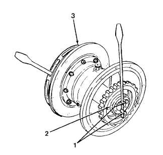
(24) Install two 3.0 inch (76.2 mm) long screws (1) in clamping ring (2).
(25) Place tire iron between two screws (1).
(26) Place second tire iron into impeller (3).
(27) Install impeller (3) by rotating impeller clockwise. Torquing not necessary. Impeller will tighten during
pump operation.
(28) Determine installed location of impeller as follows:
(a)
Measure distance (A) from volute flange, with gasket, to center of volute discharge opening with a
depth gauge.
(b)
Measure distance (B) from front flange of seal plate to center of impeller opening.
(c)
Dimension B must be within 1/32 in. 0.794 mm) of dimension A. If B dimension is greater than A
dimension A, remove shims as needed. If B dimension is less than A dimension, add shims as
needed.
5-89
|