|
| |
TM 10-4320-324-14
1-20. Cold Start System.
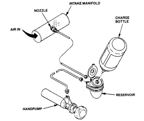
Figure 1-9. Cold Start System Functional Diagram
NOTE
The cold start system serves as an aid for starting engine at low ambient temperatures.
a.
Handpump. Pressurizes reservoir forcing starting fuel (Ether) through system.
b.
Reservoir. Has liquid level sight line --MAXI-- to ensure full servicing.
c.
Nozzle. Screwed into engine air intake manifold. Directs fluid spray toward upstream end of manifold.
1-14
|