Order this information in Print

Order this information on CD-ROM

Download in PDF Format


Click here to make tpub.com your Home Page

Page Title: Lubrication System
Back | Up | Next

Click here for a printable version

Google


Web
www.tpub.com

Home


Information Categories
.... Administration
Advancement
Aerographer
Automotive
Aviation
Combat
Construction
Diving
Draftsman
Engineering
Electronics
Food and Cooking
Math
Medical
Music
Nuclear Fundamentals
Photography
Religion
USMC
   
Products
  Educational CD-ROM's
Printed Manuals
Downloadable Books


TM 10-4320-324-14 
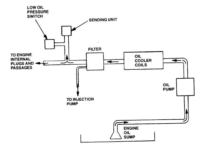
1-19.  Lubrication System. Figure 1-8.  Lubrication System Functional Diagram a. Oil Sump.  Has 8.5 qt.  (8 liter) capacity. b. Oil Pump.  Gear type element driven by gear in engine front cover. c. Oil Cooler.  Cools and directs oil to filter by engine cooling blower. d. Oil Filter.  A throw-away element which removes contaminants from oil. e. Low  Oil  Pressure  Switch.    Located  at  oil  filter  housing  discharge.    Set  to  automatically  shut  down  engine  when  oil pressure drops below 4 PSI (0.28 kg/cm2). f. Metering Plugs.  Oil jets within engine block.  Spray oil to various components. g. Fuel Injection Pump Lube Supply.  Line on one side of lube oil filter housing directs oil to injection pump spills into timing cover. 1-13

Privacy Statement - Press Release - Copyright Information. - Contact Us - Support Integrated Publishing

Integrated Publishing, Inc. - A (SDVOSB) Service Disabled Veteran Owned Small Business