|
| |
TM 10-4320-307-10
1-9
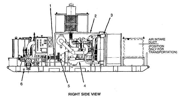
LOCATION AND DESCRIPTION OF MAJOR COMPONENTS.
FLEXIBLE COUPLING (1). The flexible coupling is used to connect the speed increaser to the pump.
ENGINE ENCLOSURE (2). The enclosure boxes the engine along its sides, top, and ends. Four hinged doors
and two removable side panels provide accessibility to the engine. The air intake duct on top and the muffler
are removable for transportation.
COOLANT RADIATOR (3). The radiator is part of the engine cooling system that maintains the engine coolant
at specified temperature during operation.
ENGINE ASSEMBLY (4). The engine is a dual turbocharged diesel engine capable of providing 450 hp at 2100
rpm while in continuous operation.
SPEED INCREASER (5). The speed increaser is used to increase engine speed to optimum pump speed of
3458 rpm. A clutch lever extends from the speed increaser gear box to a position in front of the control panel.
GROUNDING ROD CONNECTION POINT (6). The grounding rod connection point provides a connection
point for the grounding rod cable assemblies.
1-5
|