|
| |
TM 10-4320-307-10
1-9
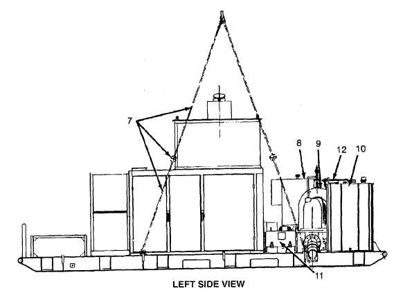
LOCATION AND DESCRIPTION OF MAJOR COMPONENTS (CONT).
LIFTING BAIL ASSEMBLY (7). A lifting bail assembly is provided to lift the pumping assembly into position.
The lifting bail assembly is connected to four locations on the skid when in use; otherwise, stored on the skid.
Spreader bars are attached between lifting bail assembly to prevent damage to pumping assembly when lifting.
CONTROL PANEL (8). The control panel encloses the pumping assembly controls and indicators, which
include a tachometer/hourmeter, lube oil pressure gauge, coolant water temperature gauge, suction pressure
gauge, discharge pressure gauge, on/off switches, malfunction lights, test switch, start/stop switch, auto/manual
switch, and engine speed/pump discharge pressure potentiometer. A work light is mounted to the top of the
control panel. The light switch and dimmer control are also mounted on the panel face.
PUMP (9). The installed pump is a three-stage centrifugal pump with a design capacity of 800 gpm.
FUEL TANK (10). The fuel tank is mounted to the skid. The fuel tank has a capacity of 110 gallons and is
designed to provide 4 hours of operation at maximum continuous power without refueling. The fuel level in the
tank is indicated by a mechanical liquid level gauge graduated from empty to full.
BATTERY BOX (11). The battery box contains four lead acid 12-volt batteries, two in series and two in parallel.
FUEL FEEDING SYSTEM (12). The fuel feeding system consists of a precleaner, hand pump, fuel feed pump,
injection pump, injectors, and dual fuel filters. The primary filter is a water separating type. Two 3-way valves
with corrosion resistant tags marked OFF, UNIT TANK, and AUXILIARY are connected in line to a 110-gallon
fuel tank.
1-6
|