|
| |
TM 9-2330-398-24
4-1.
ENGINE ASSEMBLY REPAIR (continued).
26.
Thoroughly clean and inspect each piston. Clean carbon from ring grooves and make sure that any oil holes are
open. If any piston is badly scored or buffed, loose in cylinders, has badly worn ring grooves, or otherwise is not In
good condition, replace it. Check piston clearance in cylinder 90 degrees from axis of piston pin and below oil
control ring. Clearance should be 0.0055 to 0.0075 inch (0.014 to 0.019 cm). If not, replace piston and check
cylinder wall for possible reconditioning.
NOTE
Piston and pin are matched set and are not procured separately.
27.
Each piston pin should be a thumb push fit into its piston at room temperature. If pin is excessively loose, piston.
28.
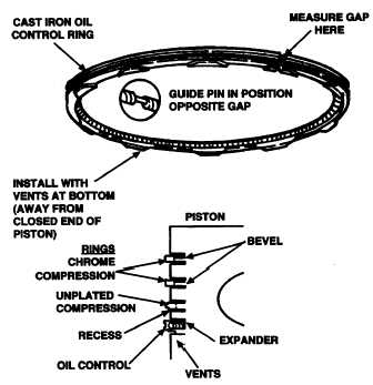
Place each piston ring into its cylinder bore and, using a feeler gage, measure gap where indicated in illustration.
Gap is shown in Table 4-1. If gap is under 0.010 inch (0.025 cm), file as follows:
a.
Place file in vise and grasp piston ring in both hands.
b.
Insert file into ring gap and move ring down entire length of file. Be sure to apply equal pressure on ring.
29.
Clean connecting rods and check each rod for defects. Check connecting rod bushings for proper clearance with
piston pin. Clearance is given in Table 4-1. If bushings are excessively worn, press them out and install one new
bushing from each side of bushing bore. Press new bushings only until flush with sides of rod to leave 0.0625 to
0.1094 inch (0.159 to 0.278cm) oil groove in center. Ream bushing inside diameter to obtain proper clearance.
Check bore in connecting rod. Bore must be open. Check connecting rod alignment on a standard alignment
fixture.
30.
Inspect connecting rod bearings for burrs,
breaks, pits, and wear. Measure clearance
between bearings and crankshaft journal (Table
4-1). If necessary, replace with new standard or
undersize bearings.
4-18
|