|
| |
TM 9-2330-398-24
3-22.
FUEL INJECTION NOZZLE REPAIR (continued).
d.
ASSEMBLY
1.
Secure nozzle holder (17) in vise, with vise jaw caps and install adapter (18) in nozzle holder (17).
2.
Install spindle (16) on nozzle holder (17).
3.
Install spring (15) on spindle (16) in nozzle holder (17) and secure with copper gasket (13) and adjusting screw
(14).
4.
Install plug (11) on protective cap (12).
5.
Loosely install protective cap (12) on adjusting screw (14).
6.
Rinse nozzle assembly (21) in clean diesel fuel.
7.
Remove all pressure from spring (15) by loosening adjusting screw (14).
8.
Remove nozzle cap (18) from nozzle holder (17), and install new gasket (20) in nozzle cap (t8).
9.
Install nozzle assembly (21) on nozzle cap (18).
10.
Loosely install nozzle cap (18) on nozzle holder (17).
CAUTION
To prevent damage to components, do not contact valve in nozzle when tightening nozzle cap nut. To
prevent damage to nozzle assembly, make sure it is centered in nozzle cap before nozzle cap is tightened.
11.
Tighten nozzle cap (21) between 50 and 55 Ib-ft (68 and 75 Nom).
12.
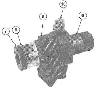
Install pipe elbow (10), adapter (9), new gasket (8), and spacer plate (7) on fuel injector (11).
3-67
|