|
| |
TM 9-2330-398-24
3-16. ENGINE AND PUMP CABINET FRAME REPLACEMENT (continued).
7.
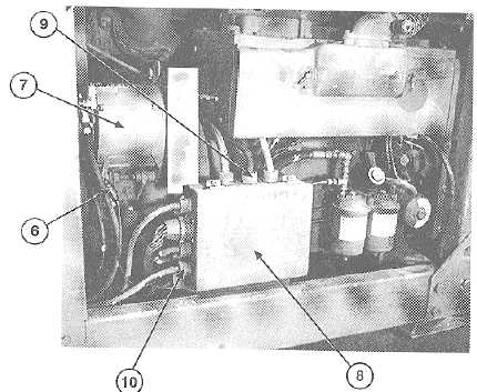
Remove 16 nuts (23), two gaskets (22), inlet line (10), and outlet line (14) from centrifugal pump (24). Discard
gaskets.
8.
Remove four screws (29) and self-locking nuts (31) and cross brace (30) from frame (26). Discard self-locking
nuts.
9.
Remove six screws (28) self-locking nuts (25) and support bracket (27) from frame (26). Discard self-locking
nuts.
10.
Position forklift under frame (26). Remove 12 self-locking nuts (34) and screws (35), and engine and pump
assembly (33) in frame (26) from semitrailer. Discard self-locking nuts.
b.
INSTALLATION
1.
Position frame (26), with engine and pump assembly (33) under semitrailer. Install 12 screws (35) and new self-
locking nuts (34) on frame (26).
2.
Install support bracket (27) and six screws (28) and new self-locking nuts (25) on frame (26).
3.
Install cross brace (30) and four screws (29) and new self-locking nuts (31) on frame (26).
4.
Install two new gaskets (22), inlet line (10), and outlet line (14) on centrifugal pump (24) with 16 nuts (23).
3-50
|