|
| |
TM 9-2330-398-24
3-16. ENGINE AND PUMP CABINET FRAME REPLACEMENT.
This Task Covers:
a. Removal
b. Installation
Initial Setup:
Tool/Test Equipment:
•
Semitrailer bonded and grounded (refer to
•
General mechanic's tool kit (Item 4, Appendix B)
TM 9-2330-398-10).
•
Forklift (Item 5, Appendix B)
•
Engine throttle cable disconnected (para 3-23).
•
Batteries removed (para 2-32).
Materials/Parts:
•
Curb-side hose trough access cover removed
•
Gasket (2) (Item 41, Appendix F)
(para 2-76).
•
Seal (2) (Item 153, Appendix F)
•
Tank drained and purged (refer to TM 9-2330-398-10).
•
Self-locking nut (4) (Item 166, Appendix F)
•
Muffler shroud removed (para 2-99).
•
Self-locking nut (12) (Item 169, Appendix F)
•
Muffler and exhaust pipe removed (para 2-99).
•
Self-locking nut (8) (Item 177, Appendix F)
Personnel Required: Two
Equipment Conditions:
•
Semitrailer uncoupled (refer to TM 9-2330-398-10).
a.
REMOVAL
1.
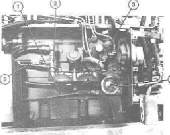
Tag and remove 1/4-inch oil pressure tube (1) from oil adapter (4). Tag and remove 1/4-inch fuel pressure tube
(5) from tee (2) on primary fuel filter (3).
2.
Disconnect two electrical leads (9 and 10) from engine electrical box (8).
3.
Disconnect electrical lead (6) from alternator (7).
4.
Remove two screws (18) and self-locking nuts
(21) securing conduit mounting plate (19) to
engine and pump cabinet frame (20). Discard
self-locking nuts.
5.
Place suitable container under inlet and outlet
lines (10 and 14). Remove four screws (12 and
17), split couplings (11 and 16), and seals (13
and 15) from pump. Discard gaskets.
6.
Place suitable container under drain plug (32) on
bottom of centrifugal pump (24). Remove drain
plug (32) and drain fuel from centrifugal pump
(24).
3-48
|