|
| |
TM 9-2350-285-20
2-126. PIPING CONTROL ASSEMBLY REPLACEMENT.
This Task Covers:
a.
Removal
b.
Installation
Initial Setup:
Tools/Test Equipment:
Equipment Conditions:
ì
General mechanic’s tool kit (Item 4,
ì
B valve assembly removed (para 2-130).
Appendix B)
ì
F valve assembly removed (para 2-130).
ì
K valve assembly removed (para 2-131).
Materials/Parts:
ì·
G valve assembly removed (para 2-135).
ì Gasket (Item 20, Appendix F)
ì
Semitrailer uncoupled (refer to TM 9-2330-398-10).
ì Self-locking nut (13) (Item 172, Appendix F)
ì
Fuel tank drained and purged (refer to TM
TM 9-2330-398-10).
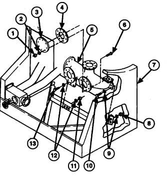
a. REMOVAL
1.
Remove eight screws (6), washers (2), and self-locking nuts (1), access cover (3), and gasket (4) from discharge
manifold (5). Discard self-locking nuts and gasket.
2.
Remove three screws (13), six washers (12), and three self-locking nuts (11) from discharge manifold (5).
Discard self-locking nuts.
3.
Remove two screws (10), four washers (9), and two self-locking nuts (8) and discharge manifold (5) from piping
control cabinet (7). Discard self-locking nuts.
b. INSTALLATION
1.
Secure discharge manifold (4) in piping control
cabinet (6) with two screws (9), four washers (8),
and two new self-locking screws (7).
2.
Install three screws (12), six washers (11), and
three new self-locking nuts (10) on discharge
manifold (6).
3.
Install access cover (2) and new gasket (3) on
discharge manifold (4) with eight screws (5), and
new self-locking nuts (1).
FOLLOW-ON MAINTENANCE:
•
Install G valve assembly (para 2-135).
•
Install B valve assembly (para 2-130).
•
Install F valve assembly (para 2-130).
•
Install K valve assembly (para 2-131).
2-278
|