|
| |
TM 9-2350-285-20
2-125. MANIFOLD VALVE ASSEMBLY REPAIR.
This Task Covers:
a.
Removal
b.
Disassembly
c.
Cleaning and Inspection d.
Assembly
e.
Installation
Initial Setup:
Tools/Test Equipment:
ì
Packing (Item 124, Appendix F)
ì
General mechanic’s tool kit (Item 4, Appendix B)
ì
Seal (2), (Item 153, Appendix F)
ì
Self-locking nut (18) (Item 172, Appendix F)
Materials/Parts:
ì
Drycleaning solvent (Item 12, Appendix C)
Equipment Conditions:
ì
Rag (Item 25, Appendix C)
ì
Semitrailer uncoupled (refer to TM 9-2330-398-10).
a. REMOVAL
1.
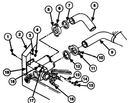
Remove two screws (5), coupling (6) seal (7), and tubing (8) from manifold valve assembly (19). Discard seal.
2.
Remove two screws (10), coupling (11), seal (12), and tubing (9) from manifold valve assembly (19). Discard
seal.
3.
Remove eight self-locking nuts (18), washers (17), studs (13), washers (14), and self-locking nuts (15) from
manifold valve assembly (19) and valve G (16). Discard self-locking nuts.
4.
Remove two screws (1), washers (3), and self-locking nuts (4) and manifold valve assembly (19) from piping
control cabinet (2). Discard self-locking nuts.
2-274
|

