|
| |
TM 9-2330-398-24
2-112. ENGINE CONTROL PANEL REPAIR.
This Task Covers:
a. Removal
b. Disassembly
c. Inspection
d. Assembly
e. Installation
Initial Setup:
Tool Test Equipment:
•
Self-locking nut (2) (Item 169, Appendix F)
•
General mechanic's tool kit (Item 4, Appendix B)
•
Self-locking nut (4) (Item 172, Appendix F)
Materials/Parts:
Equipment Conditions:
•
Lockwasher (Item 93, Appendix F)
•
Semitrailer uncoupled (refer to TM 9-2330-398-10).
•
Self-locking nut (22) (Item 166, Appendix F)
•
Negative battery cable disconnected (para 2-33).
a.
REMOVAL
WARNING
When performing electrical maintenance, ALWAYS disconnect intervehicular
electrical cable from semitrailer and disconnect semitrailer negative battery cables
at batteries. Failure to follow this warning may create a spark and explosion,
resulting in serious injury or death to personnel.
NOTE
Removal of engine control panel is not required for replacement of switches,
gages, meters, and indicator light.
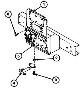
1. Release fastener (4) and open control panel
cover (1).
2. Remove six screws(6) from engine control panel
(5), and swing control panel (5) down.
3. Remove two screws (3) and self-locking nuts (2)
and fastener (4) from control panel (5). Discard
self-locking nuts.
2-236
|

