|
| |
TM 9-2330-398-24
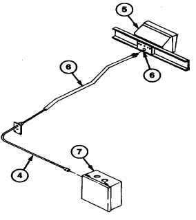
2-102. ELECTRICAL LEAD ASSEMBLY (12207081) REPLACEMENT (continued).
2.
Disconnect control panel electrical lead assembly conduit (6) from back of control panel (5).
NOTE
Connectors must be removed in order to pull electrical lead assembly through
conduit.
3.
Cut connectors from electrical lead assembly (4) and pull through conduit (6).
4.
Disconnect electrical lead assembly (4) from electrical box (7) and remove lead assembly (4).
b. INSTALLATION
NOTE
• Repair electrical lead assembly as required (para 2-101).
• Use lacing wire, electrical wire, string, or other suitable material to help pull lead
assembly through conduit.
1.
Pull lead assembly (4) through conduit (6).
2.
Install new connectors on each electrical lead assembly lead (para 2-101).
3.
Install conduit (6) on back of control panel (5).
4.
Connect electrical leads (3), jumper assemblies (2), and electrical components (1) to lead assembly (4).
5.
Close panel and cover (para 2-32e).
FOLLOW-ON MAINTENANCE:
• Disconnect ground (refer to TM 92330-398-10).
• Connect negative battery cable (para 2-33).
• Install engine control panel (para 2-112).
2-215
|