|
| |
TM 9-2330-398-24
2-62.
TIRE AND WHEEL ASSEMBLY REPLACEMENT (continued).
b.
INSTALLATION
NOTE
If inner tire and wheel assembly was removed, perform steps 1 through 4. If not, go to step 5.
CAUTION
Wheel and brakedrum have to be aligned properly during installation. If valve stem is not properly
aligned (seated) in notch, valve stem will be damaged and tire will go flat.
1.
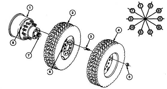
Install inner tire and wheel assembly (2) on hub and brakedrum assembly (1). Align inner tire and wheel assembly
(2) so that valve stem (6) aligns with notch (8) on hub and brakedrum assembly (1) and secure with 10 inner stud
nuts (3).
2.
Using jack, lower tire and wheel assembly (2) to the ground.
3.
Tighten 10 inner stud nuts (3) between 450 and 500 Ib-ft (610 and 678 N•m) using the sequence shown below.
4. Using jack, raise axle (7) until tire and wheel assembly (2) is off the ground.
5. Install outer tire and wheel assembly (4) on hub and brakedrum assembly (1) and secure with 10 outer stud nuts
(5).
6. Remove axle support.
7. Using jack, lower inner and outer tire and wheel assemblies (2 and 4) to the ground.
8. Tighten outer stud nuts (5) between 450 and 500 Ib-ft (610 and 678 mm) using the sequence shown below.
FOLLOW-ON MAINTENANCE:
• None
2-151
|