|
| |
TM 9-2330-398-24
2-60. SLACK ADJUSTER REPLACEMENT (continued).
d.
ADJUSTMENT
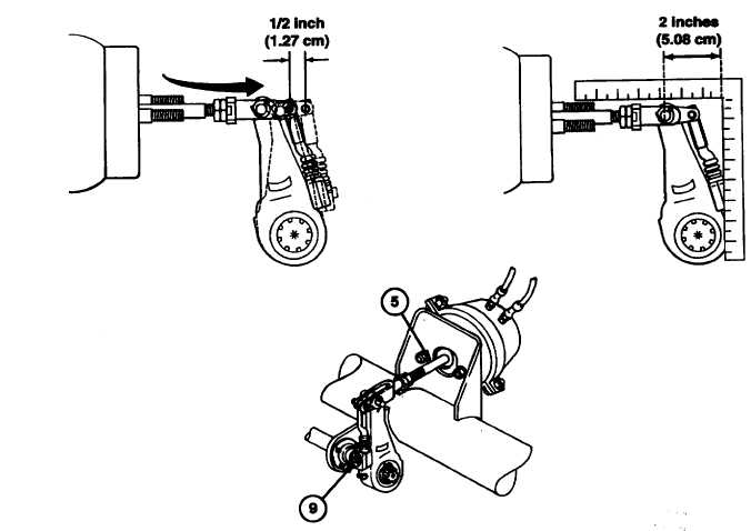
1.
Raise rear axle until wheels clear the ground. Rotate manual adjustment hex (9) clockwise until brake linings are
snug against brakedrum.
NOTE
A lot more torque is required to rotate manual adjustment hex counterclockwise
than is necessary to rotate It clockwise. Torque may be as high as 70 Ib-ft (94.9
Nm).
2.
Turn manual adjustment hex (9) counterclockwise 1/4 turn. Pull push rod (5) to confirm that push rod (5) has
approximately 0.50 inch (1.27 cm) of free travel.
3.
Apply between 90 and 95 psi (621 and 655 kPa) air pressure from towing vehicle air gage. Make and hold a full
brake application. Measure push-rod stroke. Two inches (5.08cm) is maximum stroke. If stroke exceeds the
two-inch limit, inspect all brake system components for serviceability.
FOLLOW-ON MAINTENANCE:
• Disconnect ground (refer to TM 92330-398-10).
• Uncage fail-safe chamber brakes (para 2-60).
2-130
|