|
| |
TM 55-4920-383-13&P
aircraft instruments.
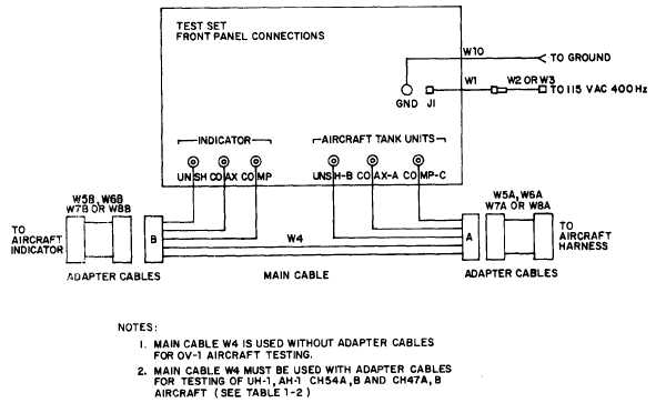
b. Referring to table 1-2 and figure 2-2, connect the appropriate adapter cables to
main cable W4. Note that the multi-pin connectors on W4 are marked A and B. The connec-
tor marked A, mates with adapter cables W5A, W6A, W7A or W8A and the connector
marked B, mates with adapter cables W5B, W6B, W7B and W8B. Adapter cables are not
needed for testing of the OV-1 aircraft fuel quantity system.
c. Connect W4 with appropriate adapter cables into aircraft wiring as shown in figure
2-2. The two branch groups of leads (fig. 2-2) must now be connected to the proper
receptacles on the Test Set front panel. Connect the three leads from the A branch of W4
to the appropriate receptacles marked UNSH B, COAX A and COMP C (18, figure 2-1)
located in the lower right corner of the Test Set front panel. Connect the three leads from
the B branch of W4 to the appropriate receptacles marked UNSH, COAX, and COMP (21)
located in the lower left corner of the Test Set front panel.
d.
Connect power and ground cables as described in paragraph 2-3.
2-12
Figure 2-2. Typical system/test set interconnection
|

