|
| |
FIG. 1-2
TM 55-4920-383-13&P
bridge. Check that capacitance bridge reads between 49.50 and 50.50 pF.
(11) Set CAPACITANCE FUNCTION switch (1) to IND TEST-A/C position and null
capacitance bridge.
Check that capacitance bridge reads between 14.50 and 15.50 pF.
(12) Set CAPACITANCE FUNCTION switch (1) to IND TEST-A/C + PROBE SIM posi-
tion and null capacitance bridge.
Check that capacitance bridge reads between 14.50 and
15.50 pF.
(13) Set CAPACITANCE FUNCTION switch (1) to IND TEST-A/C + PROBE SIM +
COMP SM position and null capacitance bridge.
Check that capacitance bridge reads between
64.50 and 65.50 pF.
g. Resistance Measurement Checkout.
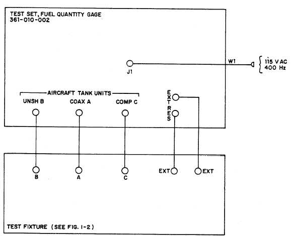
(1) Connect equipment as shown in figure 4-3.
4-10
Figure 4-3. Resistance measurement checkout, setup diagram
PIN: 047683-003
|

