|
| |
TM 55-2915-335-30&P
EQUIPMENT REQUIREMENTS AND CONSTRUCTION NOTES
1.
2.
3.
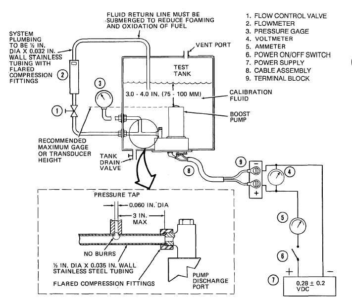
Flowmeter (2) can be analog rotometer or turbine type with digital readout. 0 to 1000 PPH readouts must be ac-
curate to ±2%. Always calibrate flowmeter (2) with the test tank-calibration fluid.
Range of digital or analog pressure gage (3) should be 0-30 psi, with readouts accurate to ±0.5%. Pressure gage or
transducer should not be positioned above pump level. (If located above tank fluid level, use clear plastic tubing to
allow static head to be measured for adjustment of pressure readout.)
Power supply (7) output must be regulated to ±0.02 VDC with current draw at 3 to 6 amperes. Readouts must be ac-
voltmeter (4) must be accurate within ±0.02 VDC at 28.0 voltage level. For accurate readout of motor supply volt-
age, voltmeter (4) must be connected across terminal block (9). Use cable assembly (8), (Item 1, Fig. B-1),
nect pump motor to terminal block (9).
Figure 5. Test Tank
D-4
|