Order this information in Print

Order this information on CD-ROM

Download in PDF Format


Click here to make tpub.com your Home Page

Page Title: Figure 2-10. Filler and Discharge and Filler and Discharge Valve Hose Assembly Assembly
Back | Up | Next

Click here for a printable version

Google


Web
www.tpub.com

Home


Information Categories
.... Administration
Advancement
Aerographer
Automotive
Aviation
Combat
Construction
Diving
Draftsman
Engineering
Electronics
Food and Cooking
Math
Medical
Music
Nuclear Fundamentals
Photography
Religion
USMC
   
Products
  Educational CD-ROM's
Printed Manuals
Downloadable Books


TM   5-5430-219-13 a. 
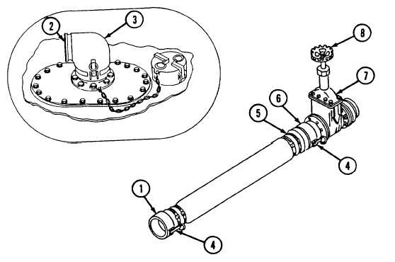
Remove   dust   cap   (1)   from   flanged   adapter   (2). (1)   Pull   cam-lever   arms   (3)   outward. (2)   Disconnect   dust   cap. b. Inspect   elbow   (4)   for   cleanliness. c . Check   to   see   that   gasket   (5)   is   in   place   and   is   properly   seated. NOTE Cam-lever  arms  must  be  pulled  inward  to  lock  and  outward  to unlock   the   elbow. d. Place   female   end   (6)   of   elbow   (4)   over   flanged   adapter   (2)   with   cam- lever   arms   (7)   in   outward   position. e . Rotate   elbow   (4)   so   that   open   end   (8)   points   to   nearest   end   of   tank. f . Lift   cam-lever   arms   (7)   and   lock   elbow   (4)   in   place. 2-5.7   Installation   of   Filler   and   Discharge   Hose   Assembly   and   Filler   and Figure   2-10. Filler   and   Discharge and  Filler  and  Discharge  Valve Hose Assembly Assembly 2-18 Discharge   Valve   Assembly.   (See   figure   2-10.)

Privacy Statement - Press Release - Copyright Information. - Contact Us - Support Integrated Publishing

Integrated Publishing, Inc. - A (SDVOSB) Service Disabled Veteran Owned Small Business